
Jul 19, 2026Case Studies & Applications
What's Wrong with Using a Simple Carbide End Mill Feeds and Speeds Calculator?
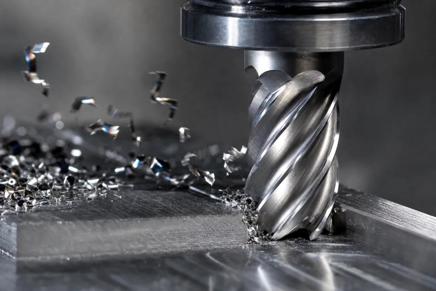
Struggling to find the right parameters for your new tool? Many machinists we talk to get stuck searching for a perfect carbide end mill feeds and speeds calculator, worried that the wrong number will lead to a broken tool or a scrapped part. The real solution isn't a single magic number, but a framework for making an informed decision based on your specific job.
A carbide end mill feeds and speeds calculator provides a theoretical starting point, not a definitive final answer[1]. It cannot account for critical real-world variables unique to your setup, such as machine rigidity, tool holder quality, coolant application[2], and the specific goals of your operation (e.g., roughing vs. finishing). Relying on a generic number without context introduces significant risk.

That simple answer might feel unsatisfying, but it's the professional truth. Instead of chasing a single number, let's explore the factors that actually determine success. Understanding these variables empowers you to move from guessing to making expert, risk-informed decisions that improve both quality and efficiency.
Why Can't a Carbide End Mill Feeds and Speeds Calculator Give a Perfect Number?
You've got the part print, the material, and the tool, so why is finding the right cutting data so difficult? It's because a simple carbide end mill feeds and speeds calculator operates in a perfect world, while you operate in a real-world shop with unique conditions.
A calculator can't ask you about your machine's history, the quality of your tool holder, or if you're prioritizing removal rate over surface finish. These variables have a massive impact on the outcome, turning a "correct" number into a recipe for failure.
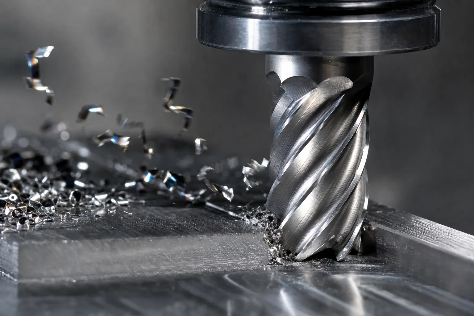
To truly dial in your process, you need to think like an engineer, not a data entry clerk. The best machinists develop a feel for how the core components of any machining operation interact. It’s about understanding the relationship between the tool, the machine, and the material you're cutting. Let's break down these critical factors that no online calculator can fully appreciate.
H3: The "Big Three" Machining Variables
Every machining operation is a balance of three key elements. A change in one requires an adjustment in the others.
- Workpiece Material: The single biggest factor. Cutting 6061-T6 aluminum is a completely different world from cutting D2 tool steel or Inconel. The material's hardness, abrasiveness, and thermal conductivity dictate the starting Surface Feet per Minute (SFM).[3] For example, soft, gummy materials require sharp cutting edges and high speeds to avoid built-up edge (BUE)[4], while hard, abrasive materials require tougher cutting edges, specialized coatings, and often lower speeds to manage heat and prevent rapid tool wear. A generic calculator might have a setting for "steel," but it can't differentiate between low-carbon 1018 steel and hardened 4140 pre-hard.
- Machine Capability: Your CNC machine's condition is a huge variable. A brand-new, rigid vertical machining center with a high-speed spindle and high-pressure through-spindle coolant can handle much more aggressive parameters than a 15-year-old machine with some wear in the box ways.
- Spindle Power & Speed: Does your machine have the horsepower to handle a heavy roughing cut? Does its spindle have the RPM capability to achieve the recommended SFM for small-diameter tools in aluminum? A calculator's recommendation is useless if your machine can't physically achieve it.[6]
- Tool Geometry: Finally, the tool itself is a complex piece of engineering. From our perspective as a manufacturer, this is where we see the most confusion. Customers often ask for feeds and speeds without specifying the tool. But a 2-flute end mill for aluminum has vastly different requirements than a 7-flute end mill designed for dynamic milling in steel.
- Coatings: A coating like Titanium Aluminum Nitride (TiAlN) is designed to perform at high temperatures when cutting steels, while a Zirconium Nitride (ZrN) or Diamond-Like Carbon (DLC) coating is better for preventing BUE in aluminum.[9] Using the wrong one can cripple performance.
A carbide end mill feeds and speeds calculator can't possibly integrate all these dynamic variables. It gives you a starting point, but you, the machinist, must provide the critical thinking.
What Are the Real Risks of Trusting a Generic Feeds and Speeds Chart?
A common question we hear from new customers is, "Just give me the numbers to plug in." The hesitation to provide a single, unqualified answer isn't about being difficult; it's about protecting you from very real and costly risks.
Relying on a generic number without understanding the context is a gamble. The potential downside—a scrapped part, a broken tool, or hours of lost machine time—is far more expensive than the few minutes it takes to properly assess the situation.
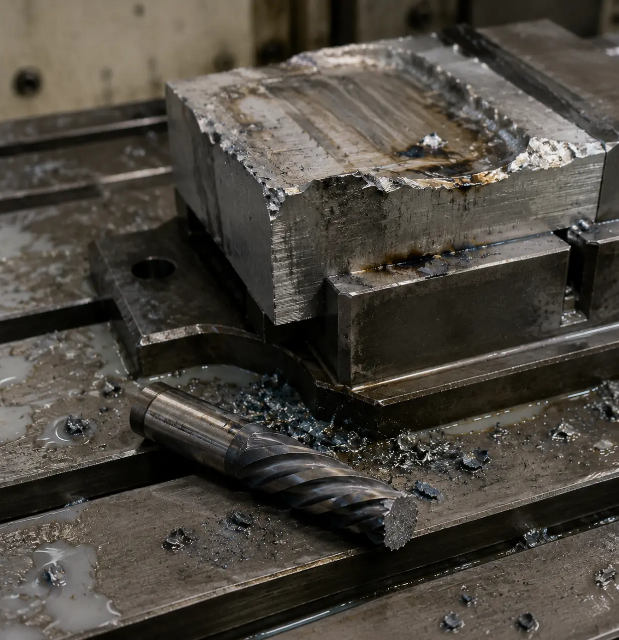
Let's dive into the specific consequences that can occur when you put blind faith in a number that wasn't designed for your unique application. These are the problems we help our customers avoid every day by encouraging a more holistic approach.
H3: Catastrophic Tool Failure
This is the most dramatic and immediate risk. Every carbide end mill is designed for a specific chip load—the thickness of the material cut by each flute. If your feed rate is too high for your spindle speed, the chip load becomes excessive.[10] This puts immense pressure on the cutting edge, leading to a sudden, catastrophic snap.[11] A $100 end mill can be destroyed in less than a second. Worse, a broken tool can damage the workpiece or even the machine spindle.
H3: Poor Surface Finish and Dimensional Inaccuracy
Even if the tool doesn't break, incorrect parameters can ruin your part.
- Chatter: This is a harmonic vibration caused by a lack of rigidity or incorrect cutting parameters.[12] It leaves a terrible, wavy pattern on the surface of your part and drastically reduces tool life. Using a calculator's RPM recommendation without considering your machine's unique resonant frequencies is a common cause of chatter.
- Tool Deflection: Pushing a tool too hard, especially a long-reach end mill, will cause it to physically bend. Even a few thousandths of an inch of deflection can cause your part to be out of tolerance.
- Rubbing: Conversely, if your feed rate is too low for your spindle speed, the chip load is too small. The flutes begin to rub against the material instead of shearing it. This generates excessive heat, causes work hardening (especially in stainless steels and superalloys), and leads to rapid tool wear and a poor finish.
H3: Reduced Productivity and Increased Hidden Costs
Many operators, afraid of tool breakage, default to being overly conservative with their parameters. While this might feel safe, it introduces a significant hidden cost: wasted cycle time. If you could safely be running a part in 5 minutes but your conservative parameters take 8 minutes, that's a 60% increase in cycle time. Across a production run of hundreds of parts, this translates to days of lost machine capacity and thousands of dollars in lost revenue.
The goal isn't just to avoid breaking the tool; it's to find the "sweet spot" of maximum metal removal rate (MRR) while maintaining acceptable tool life and part quality. A generic carbide end mill feeds and speeds calculator won't find that for you.
How Should You Actually Determine Your Machining Parameters?
So, if a generic carbide end mill feeds and speeds calculator is just a starting point, what's the professional process? It's a systematic approach that combines manufacturer data with real-world observation and adjustment.
The goal is to move from a theoretical guess to an optimized process proven on your machine, with your material, and your tools. It's about building confidence and repeatability.

This four-step method is what we recommend to our customers. It transforms the intimidating task of "finding feeds and speeds" into a manageable, logical workflow that puts you in control.
Step 1: Start with Manufacturer Recommendations
The people who designed and built your end mill are your best source of starting data. At QT TOOLS, we provide detailed charts that offer starting parameters based on the specific tool geometry and the material being cut. These are not magic numbers; they are lab-tested baselines developed under controlled conditions. They are far more reliable than a generic online calculator that doesn't know if you're using a 3-flute or 6-flute tool.
Step 2: Define Your Goal (Roughing vs. Finishing)
Are you trying to remove a massive amount of material quickly, or are you trying to produce a mirror-like surface finish on the final pass? Your strategy and parameters will be completely different.
- Roughing: The priority is Metal Removal Rate (MRR). You'll typically use a larger depth of cut (DOC) and stepover (WOC), and you might be willing to accept a shorter tool life to maximize throughput.
- Finishing: The priority is surface finish and dimensional accuracy. You'll use a very light DOC and WOC, and you'll adjust speeds and feeds to eliminate chatter and achieve the desired chip load for a clean shear.
Step 3: Perform a Test Cut and Observe
This is the most critical step. Start with the manufacturer's recommendations, often beginning at the more conservative end of the suggested range. Then, run a short test cut and use your senses.
- Listen: What does it sound like? A smooth, consistent hum is good. A high-pitched squeal or a low, rumbling chatter is bad.
- Look: What do the chips look like? For steels, well-formed, "6" or "9" shaped chips that have a silver or light straw color are ideal. Blue, black, or red chips mean you have excessive heat. For aluminum, the chips should be clean and consistent, not sticky or welded together.
- Feel: Check the part and the tool (once the spindle is stopped safely!). Is there excessive heat? Is the surface finish acceptable?
Step 4: Adjust Incrementally and Document
Based on your observations, make small, incremental adjustments. Don't change multiple variables at once. If it's too loud, try reducing your RPM first. If your chips are blue, try increasing your feed rate to carry more heat away in the chip.
Symptom Observed | Potential Cause | Suggested Adjustment (Change one at a time) |
|---|---|---|
Loud Screeching / Chatter | Tool vibration, high RPM, tool deflection | Reduce RPM by 10%. Reduce tool stickout. Use a more rigid tool holder. |
Blue/Burnt Chips (in Steel) | Excessive heat, RPM too high or feed too low | Increase feed rate by 10-15%. Reduce RPM. Verify coolant is effective. |
Tool Breaks Immediately | Chip load too high or severe chip packing | Reduce feed rate by 50%. Reduce axial depth of cut. Use air blast for chip evacuation. |
Poor, Streaky Surface Finish | Rubbing (chip load too low), tool wear | Increase feed rate to achieve target chip load. Check tool for a worn cutting edge. |
Built-Up Edge (in Aluminum) | Material welding to the cutting edge | Increase RPM. Use a coated tool (ZrN or DLC). Improve coolant/lubrication. |
Once you find the "sweet spot" for a particular job, write it down! Documenting your proven parameters saves you from having to reinvent the wheel the next time a similar job comes up.
Frequently Asked Questions
What is a good starting chip load for a carbide end mill?
This depends entirely on the tool diameter and workpiece material. For general-purpose roughing in steel with a 1/2" end mill, a starting chip load might be 0.003"-0.005" per tooth. For aluminum, it could be much higher, around 0.006"-0.010". Always start with the manufacturer's recommendation for your specific tool.
How does flute count affect feeds and speeds?
More flutes mean you can increase the table feed rate while maintaining the same chip load per tooth. For example, if a 4-flute tool runs at 40 IPM, a 6-flute tool could theoretically run at 60 IPM at the same RPM and chip load. However, more flutes mean less space for chip evacuation, making them better for finishing and dynamic milling rather than deep slotting.
Why are my chips turning blue when cutting steel?
Blue chips are a clear sign of excessive heat. This is typically caused by your cutting speed (RPM) being too high for the material, or your feed rate being too low (causing rubbing). First, try increasing your feed rate to carry more heat away in the chip. If that doesn't work, reduce your RPM.
Should I always use coolant?
Not always. For many steel applications with modern coated carbide tools, running dry with a strong air blast is preferred. The coatings are designed to work at high temperatures, and the thermal shock from intermittent coolant can cause micro-fractures in the carbide. For aluminum, stainless steels, and titanium, flood coolant is almost always necessary to prevent chip welding and manage heat.
Conclusion
The search for a perfect carbide end mill feeds and speeds calculator is understandable, but ultimately misguided. It treats a complex, dynamic process as a simple math problem. True optimization comes from understanding the core variables: your material, your machine, and your specific cutting tool. By using manufacturer data as a starting point, performing an observant test cut, and making incremental adjustments, you can develop reliable, high-performance parameters that far exceed what any generic calculator can provide. This approach not only prevents costly mistakes but also unlocks your shop's full potential for productivity and quality.
At QT TOOLS, we believe our job is to be more than just a supplier. We are your partner in productivity. If you're tired of guessing, contact our team today. We can help you select the right end mill for your application and provide the expert guidance you need to go beyond a generic calculator and achieve optimal results.
1
"Helical - MACHINING GUIDEBOOK", https://web.mae.ufl.edu/designlab/Advanced%20Manufacturing/Helical_Machining_Guidebook.pdf. A university machining reference describes calculated milling speeds and feeds as recommended starting conditions that should be adjusted according to the machine, tooling, workholding, coolant, and observed cutting performance. Evidence role: general_support; source type: education. Supports: Feeds-and-speeds calculations are commonly treated as initial cutting-condition estimates that must be validated against the actual machining system.. Scope note: This would support the principle generally, not the performance of any specific calculator.
2
"Effect of Cutting Fluid on Milled Surface Quality and Tool Life ... - PMC", https://pmc.ncbi.nlm.nih.gov/articles/PMC10056421/. Machining research links machine-tool structural stiffness, toolholding conditions, and coolant or lubrication strategy to milling stability, temperature control, tool wear, and resulting surface integrity. Evidence role: mechanism; source type: paper. Supports: Rigidity, toolholding, and coolant/lubrication conditions influence milling stability, heat generation, tool wear, and surface quality.. Scope note: The source would provide mechanistic support across machining studies rather than quantify the effect for the reader’s exact machine setup.
3
"CUTTING TOOL TECHNOLOGY", https://www.egr.msu.edu/~pkwon/me477/cuttingtool. Machining education sources explain that recommended cutting speed is selected with reference to workpiece material properties, including hardness, abrasiveness, and heat-transfer behavior, because these properties affect cutting forces, temperature, and tool wear. Evidence role: mechanism; source type: education. Supports: Material properties such as hardness, abrasiveness, and thermal conductivity are used to select initial cutting speeds in milling.. Scope note: This supports the general selection logic, not a particular SFM value for a specific alloy.
4
"effect of cutting speed in the turning process of aisi 1045 steel ...", https://www.academia.edu/43680779/EFFECT_OF_CUTTING_SPEED_IN_THE_TURNING_PROCESS_OF_AISI_1045_STEEL_ON_CUTTING_FORCE_AND_BUILT_UP_EDGE_BUE_CHARACTERISTICS_OF_CARBIDE_CUTTING_TOOL. Studies of built-up edge formation report that ductile work materials can adhere to the cutting edge under certain speed, temperature, and friction conditions, and that sharper cutting edges and suitable cutting speeds can reduce adhesion in some machining operations. Evidence role: mechanism; source type: paper. Supports: Built-up edge is associated with ductile material adhesion at the cutting edge and can be influenced by tool sharpness and cutting speed.. Scope note: The effect depends on alloy, coating, lubrication, and cutting geometry, so the source would be contextual rather than a universal rule.
5
"Tooling and Workholding", https://ise.ncsu.edu/processes/wp-content/uploads/sites/11/2013/08/ToolingWorkholding-ES0350.pdf. Machining dynamics literature shows that the stiffness and damping of the machine-tool-workpiece system, including workholding and toolholding, influence chatter stability limits and thereby affect attainable cutting force, surface finish, and tool life. Evidence role: mechanism; source type: paper. Supports: Lower stiffness in the machine-tool-workpiece system increases susceptibility to vibration or chatter, affecting surface finish and tool life.. Scope note: The source would not rank specific holder types unless it directly tests them.
6
"Fablab Speed and Feeds Calculator", https://pub.pages.cba.mit.edu/feed_speeds/. Machining references explain that cutting conditions must be checked against spindle speed, torque, and power limits because recommended cutting speeds or material-removal rates may exceed the physical capacity of a given machine tool. Evidence role: mechanism; source type: education. Supports: Spindle speed, power, and torque limits constrain whether recommended cutting parameters can be achieved in milling.. Scope note: This supports the engineering constraint generally, not the capability of any named CNC machine.
7
"Helical - MACHINING GUIDEBOOK", https://web.mae.ufl.edu/designlab/Advanced%20Manufacturing/Helical_Machining_Guidebook.pdf. Milling cutter references state that table feed is proportional to the number of teeth at a fixed chip load and spindle speed, while additional flutes reduce flute gullets and chip space, which can limit chip evacuation in slotting or deep cuts. Evidence role: mechanism; source type: education. Supports: Flute count affects feed-rate calculation and chip evacuation capacity in end milling.. Scope note: The suitability for deep slotting also depends on flute geometry, coolant or air blast, material, and axial depth.
8
"Helical - MACHINING GUIDEBOOK", https://web.mae.ufl.edu/designlab/Advanced%20Manufacturing/Helical_Machining_Guidebook.pdf. Tool-geometry references explain that end-mill helix angle affects chip flow, axial force components, and cutting-edge support, which is why higher and lower helix designs are selected for different material and stability requirements. Evidence role: mechanism; source type: education. Supports: Helix angle affects chip flow, cutting forces, and cutting-edge strength in end mills.. Scope note: The exact 45° and 30° values are common design examples and may vary by manufacturer and cutter family.
9
"Influences of TiAlN Coating on Cutting Temperature during Orthogonal ...", https://www.mdpi.com/2079-6412/9/6/355. Cutting-tool coating studies report that TiAlN-based coatings offer high-temperature oxidation resistance in steel machining, while low-friction coatings such as DLC and some ZrN systems can reduce aluminum adhesion and built-up edge under suitable conditions. Evidence role: mechanism; source type: paper. Supports: Different tool coatings have different high-temperature oxidation, friction, and adhesion behaviors relevant to steel and aluminum machining.. Scope note: The source would support coating tendencies, not guarantee performance for every tool, alloy, or coolant condition.
10
"TA Speeds and Feeds Assessment", https://web.mae.ufl.edu/designlab/Advanced%20Manufacturing/Speeds%20and%20Feeds/EML2322L%20TA%20Speeds%20&%20Feeds%20Assessment.xlsx. Machining references define chip load per tooth as feed rate divided by the product of spindle speed and number of teeth, so increasing feed rate at constant RPM and flute count increases the chip thickness removed by each flute. Evidence role: definition; source type: education. Supports: Chip load per tooth is calculated from feed rate, spindle speed, and number of cutting teeth.. Scope note: The formula gives nominal chip load and does not account for runout, engagement angle, or tool deflection.
11
"Cutting Load Capacity of End Mills with Complex Geometry", https://research.sabanciuniv.edu/231/1/3011800000736.pdf. Research on milling tool failure shows that excessive feed per tooth increases cutting forces and mechanical loading on carbide cutting edges, which can promote edge chipping or brittle fracture when the load exceeds the tool’s strength or stability limits. Evidence role: mechanism; source type: paper. Supports: Excessive chip load increases cutting forces and can contribute to chipping or fracture of brittle carbide cutting edges.. Scope note: Tool breakage may also involve runout, chatter, impact, chip packing, or pre-existing damage.
12
"An Investigation of Cutting Tool Chatter Vibration in Machine ...", https://scholarworks.uni.edu/cgi/viewcontent.cgi?article=4664&context=grp. Machining dynamics literature defines chatter as a self-excited vibration arising from interaction between the cutting process and the machine-tool structure, with stability affected by system stiffness, damping, spindle speed, depth of cut, and other cutting parameters. Evidence role: definition; source type: paper. Supports: Milling chatter is a vibration phenomenon related to the dynamic stiffness of the machining system and selected cutting parameters.. Scope note: Calling all chatter “harmonic” is a simplification; detailed sources distinguish regenerative and mode-coupling mechanisms.