
Jul 24, 2026Case Studies & Applications
What Makes the Best Long Carbide End Mill?
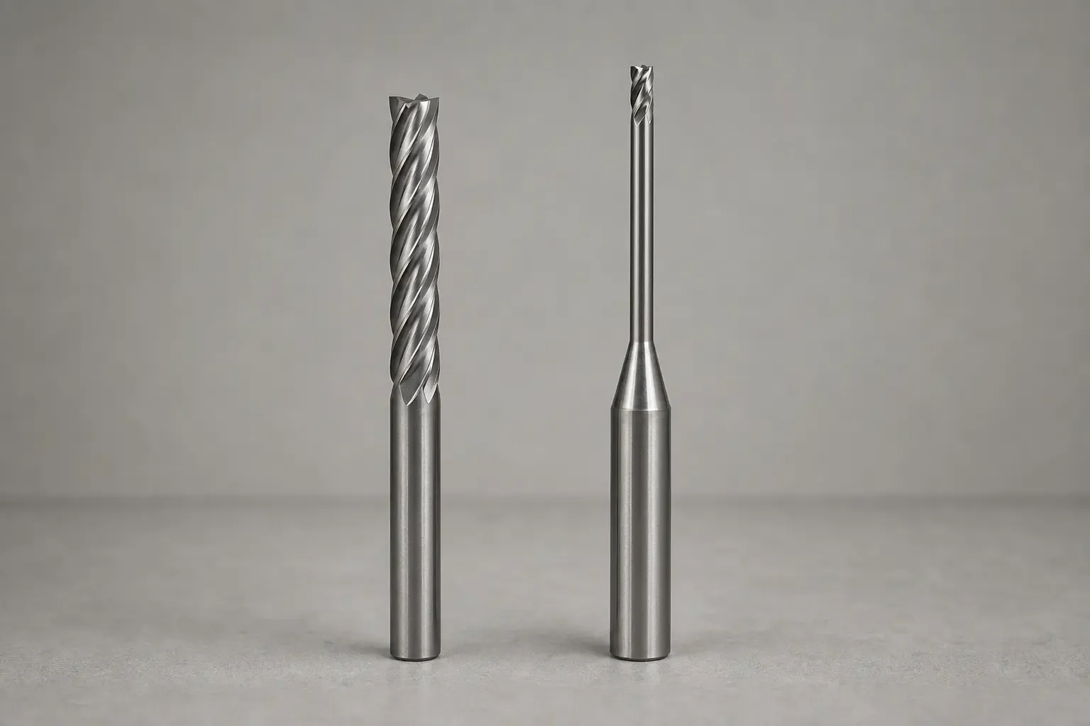
Are you struggling to find the right tool for machining deep pockets or hard-to-reach features? The search for a long carbide end mill can be frustrating, as a poor choice often leads to chatter, bad surface finish, or a catastrophic tool failure that scraps an expensive part. The solution isn't about finding a single "best" tool, but adopting a framework to choose the right tool for your specific job by managing risk.
The best long carbide end mill is not a specific brand or model, but the one whose length, diameter, flute design, and coating are correctly matched to the specific material, machine rigidity, and required depth of cut. The key is to select the shortest and most rigid tool possible that can still accomplish the task, minimizing the risk of deflection and vibration.
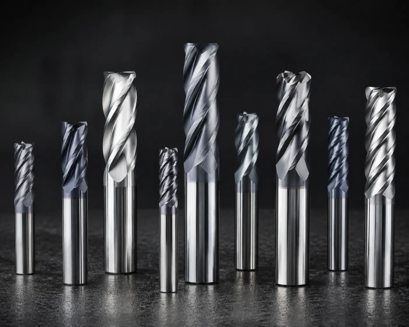
Choosing the right tool goes beyond simple catalog specs. It requires a shift in thinking from "what's the longest tool?" to "what's the most stable way to achieve my required reach?" In this article, I'll share the key principles I discuss with customers every day to help them navigate these choices and avoid costly mistakes.
How Does Length Affect a Long Carbide End Mill's Performance?
It's natural to see a long tool and think it's the perfect solution for reaching deep into a part. However, from a machining physics perspective, excessive length is the enemy of rigidity. This introduces deflection and vibration—the primary causes of poor cuts and broken tools. Let's reframe the problem from "reach" to "rigidity management."
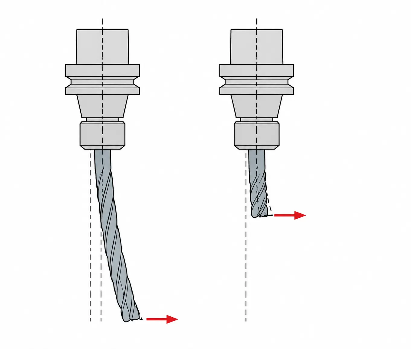
The performance of a long carbide end mill is dictated by its rigidity, which decreases dramatically as its unsupported length increases[1]. This makes the tool prone to bending under cutting forces, a phenomenon known as deflection, which leads to chatter, dimensional inaccuracies, and potential tool breakage.
The Critical Length-to-Diameter (L:D) Ratio
The most important concept to understand with any extended-reach tool is the length-to-diameter ratio, or L:D. This ratio compares the tool's effective cutting length to its cutting diameter.
- A 10mm diameter end mill with a 30mm length of cut has a 3:1 L:D ratio. This is very rigid and stable.
- The same 10mm diameter tool with a 80mm length of cut has an 8:1 L:D ratio. This is significantly less rigid.
The problem is that rigidity doesn't decrease in a straight line; it decreases exponentially. Doubling the L:D ratio doesn't just halve the rigidity; it reduces it by a factor of nearly eight[2]. This is why a small increase in length can have such a massive negative impact on performance.
As a general guideline from my consultations:
- Up to 3:1 L:D: Considered standard, stable for aggressive roughing and finishing.
- 4:1 to 6:1 L:D: Requires a reduction in cutting parameters (feed rate, depth of cut). More suitable for semi-finishing and finishing.
- 7:1 L:D and above: This is specialist territory. It demands very light cutting forces, a rigid machine setup, and careful control of speeds and feeds to prevent vibration.[3] These are almost exclusively for finishing passes.
The Real Cost of Deflection
Deflection isn't just an academic concept; it has expensive, real-world consequences. When a long carbide end mill deflects or bends mid-cut, it causes a cascade of problems:
- Poor Surface Finish: The tool vibrates against the workpiece, leaving behind a rough, chattered surface.
- Dimensional Inaccuracy: If you're trying to mill a straight wall in a deep pocket, a deflecting tool will cut a tapered wall, wider at the top than at the bottom[4].
- Premature Tool Wear: Vibration causes the cutting edge to chip and wear down rapidly.
- Catastrophic Tool Breakage: This is the ultimate risk. The cost isn't just the broken 10,000 mold or a critical aerospace component, plus the machine downtime.
This is why I always frame the selection of a long tool as a risk management decision. A slightly more expensive but more rigid tool is cheap insurance against scrapping a valuable part.
Should I Choose a Long Flute or Just a Long Reach End Mill?
A common question I get from customers is, "I need to cut a 3-inch deep pocket, so I need a tool with 3-inch flutes, right?" This seems logical, but it's often the most direct path to failure. Long flutes severely compromise the tool's core strength, increasing the risk of both deflection and chip packing.
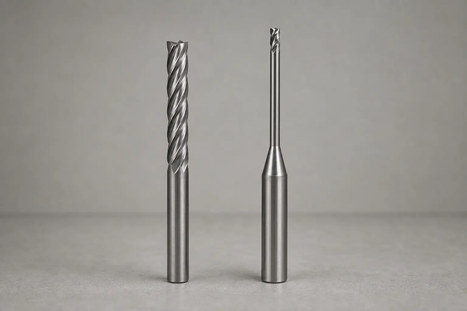
For deep pocket access where you are not cutting along the entire wall, an extended reach (or "necked") long carbide end mill is vastly superior to one with full-length flutes[5]. The extended reach design maintains a thicker, more rigid core by using a shorter cutting section, providing stability while still allowing the tool to reach deep into the part.
When to Use a Long Flute Length
There is a time and place for an end mill with a long length of cut (LOC). You should only select a tool where the flute length matches the cutting depth if your application requires it. These applications include:
- Wall Finishing: Machining a tall, straight wall in a single finishing pass to avoid a blend line.
- Full-Width Slotting: Creating a deep slot where the tool is engaged across its entire diameter.
- Edge Trimming: Trimming the edge of a thick plate.
In these specific cases, the flutes are necessary to perform the cut and evacuate chips. However, if you are simply trying to reach a feature at the bottom of a pocket, using a tool with excessively long flutes is a mistake. The reduced core diameter makes the tool behave like a wet noodle[6], and the long flutes provide nowhere for chips to go in a deep, confined pocket, leading to chip packing and tool breakage.
The Power of the Extended Reach Design
A much better solution for deep-pocketing is the extended reach end mill. This tool is designed with three distinct sections:
- Standard Length Flutes: The cutting portion of the tool, typically with a length of cut around 1.5 to 2 times the diameter. This is the only part that should be engaged with the material.
- Reduced "Neck" or "Relief": A section behind the flutes that is ground to a slightly smaller diameter than the cutting diameter. This provides clearance so the tool shank doesn't rub against the walls of the pocket.
- Full-Diameter Shank: The main body of the tool, which provides the maximum possible rigidity and strength for holding in the tool holder.
By using a short, strong cutting section and a solid, relieved shank for reach, this design maximizes rigidity—the single most important factor for success with a long carbide end mill. It's the difference between trying to stir paint with a long piece of cooked spaghetti versus a solid metal rod.
What are the Key Selection Questions for a Long Carbide End Mill?
When a customer comes to me looking for a long tool, I don't start by showing them a catalog. Instead, I walk them through a series of questions. This process turns a confusing search into a clear decision by systematically defining the problem. Answering these questions will guide you to the perfect tool for your job.
To select the right long carbide end mill, you must ask: 1) What material am I cutting? 2) What is the required reach versus the actual depth of cut? 3) How rigid is my machine and workholding? 4) Am I roughing or finishing? The answers determine the ideal geometry, coating, and parameters.
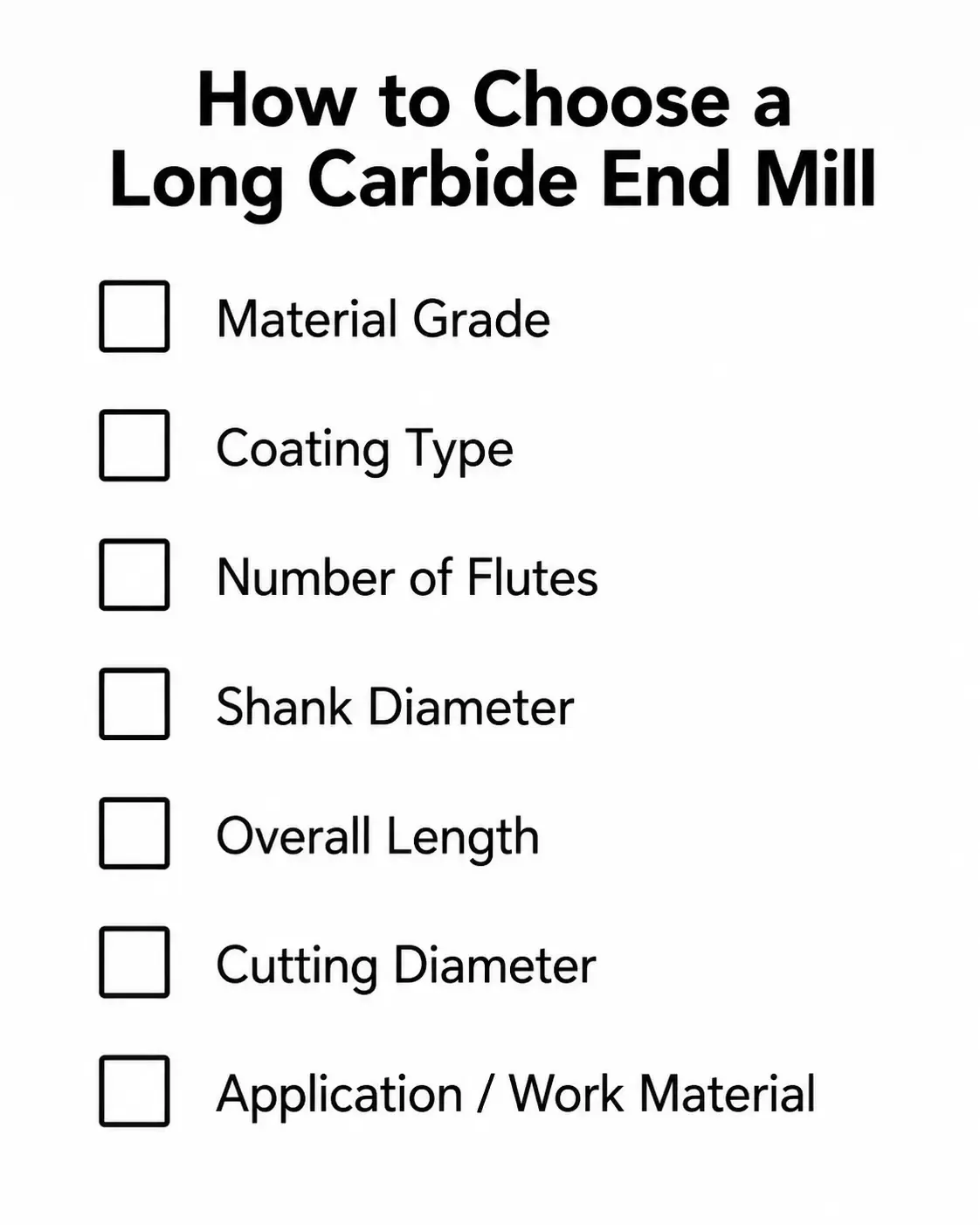
Let's break down each of these critical questions.
H3: What Material Are You Cutting?
The workpiece material dictates the fundamental geometry and coating of the end mill.
- Aluminum and Soft Metals: These materials produce long, stringy chips. You'll want fewer flutes (2 or 3) to provide more room for chip evacuation.[7] A sharp, polished cutting edge is key, and often an uncoated tool or one with a slick, non-stick coating like DLC (Diamond-Like Carbon) works best[8].
- Steels and Stainless Steels: These are tougher and generate more heat. You'll need more flutes (4 or 5) for a better finish and stability. A heat-resistant coating like AlTiN (Aluminum Titanium Nitride) is essential to protect the cutting edge from breaking down.[9]
- Hardened Steels and Superalloys: This is the most demanding category. It requires tools with 5 to 7 flutes (or more), often with a variable helix or pitch to disrupt harmonic vibrations (chatter)[10]. Advanced coatings like nACo or TiSiN that maintain hardness at extreme temperatures are a must.
H3: What Is Your Reach vs. Depth of Cut?
This is where we apply the lesson from the previous section. Be precise.
- Reach: The total distance from the tool holder to the furthest point you need to machine.
- Depth of Cut (DOC): The actual axial length of the feature you are machining.
If your reach is 4 inches but your DOC is only 0.5 inches, you absolutely need an extended reach end mill with a short flute length. If your reach and DOC are both 3 inches for a wall finishing pass, then a long-flute tool is appropriate. Don't buy more flute length than you need to cut.
H3: How Rigid Is Your Machine and Setup?
Be brutally honest here. The most advanced long carbide end mill will fail in a weak setup.
- Machine Tool: A large, rigid CAT50 or HSK100 machine can handle much longer L:D ratios than a smaller CAT40 or BT30 machine. Older machines with worn components are also less rigid.
- Workholding: Is the part held securely in a robust vise or fixture close to the machine table, or is it perched precariously on tall jaws? Any instability in the setup will be amplified by the long tool.
A less rigid setup means you must be more conservative. Use a larger diameter tool, a shorter L:D ratio, and much lighter cutting parameters.
H3: Are You Roughing or Finishing?
Your goal determines the tool and strategy.
- Roughing: The goal is maximum material removal rate (MRR). With a long tool, this means using a "high-feed milling" strategy: a very small axial depth of cut (DOC) but a very high feed rate. This directs cutting forces axially up into the spindle, which is much more stable than high radial forces that push the tool sideways and cause deflection.[12]
- Finishing: The goal is dimensional accuracy and surface finish. Here, you'll use a very light radial depth of cut (often called "peel milling" or "high-speed machining") and a full axial depth of cut. Because the cutting forces are so low, you can often use a tool with a higher L:D ratio to achieve a perfect wall finish in one pass.
Frequently Asked Questions
Can I use a long carbide end mill for roughing?
Yes, but with significant adjustments. For effective roughing, use the shortest possible tool, prioritize a larger diameter to maintain rigidity, and adopt a high-feed, low-depth-of-cut strategy. This approach minimizes the radial cutting forces that cause deflection and vibration, directing pressure axially into the machine spindle.
What's more important for a long end mill: coating or carbide grade?
Both are critical, but their priority shifts. For a long carbide end mill, geometry and rigidity are the most important factors for success. First, select the most rigid tool possible (largest diameter, shortest flute/longest reach). Then, the carbide grade provides the necessary strength and toughness, while the coating adds vital heat resistance and lubricity to manage the difficult cutting conditions.
How do I reduce chatter with a long end mill?
Chatter is a symptom of vibration. You can combat it by: 1) Increasing rigidity by using a larger diameter or shorter tool. 2) Using an end mill with variable helix/pitch geometry designed to disrupt harmonics. 3) Reducing your radial depth of cut and/or increasing your feed rate. 4) Adjusting your spindle speed (RPM) up or down to find a stable cutting frequency.
Conclusion
The search for the perfect long carbide end mill is not about finding one magical tool, but about mastering a process of risk assessment. By shifting your focus from "length" to "rigidity," you can make smarter choices that protect your workpiece, extend tool life, and improve your bottom line. Always remember to select the shortest, stoutest tool that can do the job. Understand the critical difference between required reach and actual depth of cut, and be honest about the rigidity of your machine setup. This framework turns a gamble into a calculated, successful manufacturing decision.
If you are facing a challenging application and need guidance selecting the right tooling, our team at QT TOOLS has years of experience helping customers find the most cost-effective and reliable solutions. Contact us today for a consultation and let us help you find the competitive advantage you need.
1
"Identification of a cantilever beam's spatially uncertain stiffness", https://pmc.ncbi.nlm.nih.gov/articles/PMC9860023/. A machining-dynamics or mechanical-design source may be cited to support the statement that increasing tool overhang reduces bending stiffness and increases tool deflection under cutting loads; this support is based on the standard cantilever-beam approximation rather than a test of the specific tool described here. Evidence role: mechanism; source type: research. Supports: A source should explain that an end mill can be modeled approximately as a cantilevered beam and that increased overhang reduces stiffness and increases deflection under cutting forces.. Scope note: Contextual support; the source may not evaluate this exact carbide end mill geometry.
2
"Vibrations of Cantilever Beams:", http://emweb.unl.edu/mechanics-pages/scott-whitney/325hweb/beams.htm. A mechanics-of-materials reference may be cited to support that, for a cantilever beam under comparable loading and section properties, stiffness scales approximately with 1/L³, meaning that doubling unsupported length reduces stiffness to about one-eighth. Evidence role: mechanism; source type: education. Supports: A source should support the beam-deflection relationship in which cantilever stiffness varies inversely with the cube of length, so doubling length reduces stiffness to roughly one-eighth when other variables are constant.. Scope note: This is an idealized beam-theory relationship and does not account for tool-holder compliance, flute geometry, or dynamic cutting effects.
3
"Research on the influence of cutter overhang length on robotic milling ...", https://pmc.ncbi.nlm.nih.gov/articles/PMC11496886/. A peer-reviewed study on end-milling dynamics may be cited to support that long-overhang tools are more prone to chatter and deflection and therefore require reduced cutting forces and careful parameter selection. Evidence role: general_support; source type: paper. Supports: A source should discuss the higher susceptibility of long, slender end mills to chatter and deflection and the need to reduce cutting loads as overhang increases.. Scope note: The source may support the principle without prescribing the exact 7:1 threshold used in the article.
4
"What is reasonable tool deflection when side milling steel ...", https://www.facebook.com/groups/769782850345135/posts/1979442756045799/. A study of end-milling accuracy may be cited to support that cutter deflection under lateral cutting forces contributes to geometric error in milled walls, including taper or form deviation. Evidence role: mechanism; source type: paper. Supports: A source should show that cutter deflection affects machined surface geometry and can cause dimensional deviations in side-wall milling.. Scope note: The source may describe dimensional error generally rather than the exact top-wide, bottom-narrow wall form stated here.
5
"Reduced Neck End Mills", https://www.helicaltool.com/products/tool-type/reduced-neck-end-mills. A neutral tooling or manufacturing reference may be cited to support that extended-reach, neck-relieved end mills use shorter cutting lengths and relieved shanks to improve clearance and retain greater stiffness than unnecessarily long-flute tools. Evidence role: general_support; source type: institution. Supports: A source should explain that shorter flute sections and relieved necks can preserve core strength and provide clearance for deep-reach applications.. Scope note: This supports the design rationale but does not prove that the design is superior in every deep-pocket application.
6
"End Mill Lengths: The Long & Short Of It", https://solutions.travers.com/metalworking-machining/milling/choosing-the-right-end-mill-length?hs_amp=true. A manufacturing-engineering source may be cited to support that increasing flute length and reducing cutter core cross-section can decrease bending stiffness and increase susceptibility to deflection. Evidence role: mechanism; source type: research. Supports: A source should support the relationship between flute geometry, reduced core cross-section, and lower bending stiffness or strength in milling cutters.. Scope note: The source would substantiate the mechanical principle, not the article's informal metaphor.
7
"Helical - MACHINING GUIDEBOOK", https://web.mae.ufl.edu/designlab/Advanced%20Manufacturing/Helical_Machining_Guidebook.pdf. A machining education reference may be cited to support that end mills with fewer flutes provide larger chip spaces, which is commonly advantageous for evacuating chips when milling aluminum and other soft, ductile materials. Evidence role: general_support; source type: education. Supports: A source should explain that fewer flutes provide larger chip gullets, which can aid chip evacuation in aluminum machining.. Scope note: The source may present this as common practice rather than a universal rule for every aluminum alloy or cutting condition.
8
"Performance of carbide tools coated with DLC in the ...", https://www.academia.edu/80693029/Performance_of_carbide_tools_coated_with_DLC_in_the_drilling_of_SAE_323_aluminum_alloy. A tribology or cutting-tool study may be cited to support that diamond-like carbon coatings can reduce friction and material adhesion when machining aluminum alloys. Evidence role: mechanism; source type: paper. Supports: A source should support that DLC coatings have low friction and can reduce adhesion or built-up edge in aluminum machining.. Scope note: This supports the coating mechanism and reported performance in studied conditions, but it does not prove DLC is the best choice for all aluminum milling operations.
9
"Cutting Performance of Different Coated Micro End Mills in ...", https://pmc.ncbi.nlm.nih.gov/articles/PMC6267563/. A coating-performance study may be cited to support that AlTiN coatings can improve oxidation resistance and thermal stability of carbide cutting tools in steel machining. Evidence role: mechanism; source type: paper. Supports: A source should show that AlTiN coatings improve hot hardness, oxidation resistance, or thermal protection of cutting tools used in steel machining.. Scope note: The source would support AlTiN's heat-resistance role but may not justify the absolute claim that it is essential in every steel-milling case.
10
"Chatter Stability of Machining Operations", https://academy.cba.mit.edu/classes/computer_machining/chatter.pdf. A machining-dynamics study may be cited to support that variable-pitch or variable-helix milling cutters can improve chatter stability by disturbing the phase relationship that drives regenerative vibration. Evidence role: mechanism; source type: paper. Supports: A source should explain or demonstrate that variable pitch or variable helix cutters can improve milling stability by altering tooth passing dynamics and reducing regenerative chatter.. Scope note: The magnitude of chatter reduction depends on cutter design, work material, spindle speed, and machine-tool dynamics.
11
"Clamping Fatigue Properties of Shrink-Fit Holder - PMC - NIH", https://pmc.ncbi.nlm.nih.gov/articles/PMC9412440/. An independent study of milling toolholders may be cited to support that toolholder runout, clamping stiffness, and concentricity influence milling performance, with shrink-fit or hydraulic holders often evaluated as higher-precision options than conventional collet systems. Evidence role: general_support; source type: paper. Supports: A source should compare toolholder runout, stiffness, or clamping characteristics and explain their importance in milling accuracy and vibration control.. Scope note: The source may not rank every ER, hydraulic, and shrink-fit holder design, and actual performance varies by product quality and setup.
12
"Milling force model for asymmetric end-mills during high-feed milling on ...", https://upcommons.upc.edu/bitstreams/9b8d5f69-e149-40a1-a86f-fa4d97d86fd3/download. A milling-force analysis may be cited to support that high-feed milling strategies and cutter geometries can shift a larger share of cutting load into the axial direction, reducing lateral tool deflection compared with strategies that impose higher radial forces. Evidence role: mechanism; source type: paper. Supports: A source should explain how high-feed cutter geometry and shallow depths of cut affect cutting-force components, often increasing the axial component relative to radial loading.. Scope note: The force distribution depends on cutter geometry, lead angle, engagement, material, and cutting parameters.