
Aug 4, 2026Industry News & QT Updates
How Does Chip Load for a Carbide End Mill Affect Your Bottom Line?
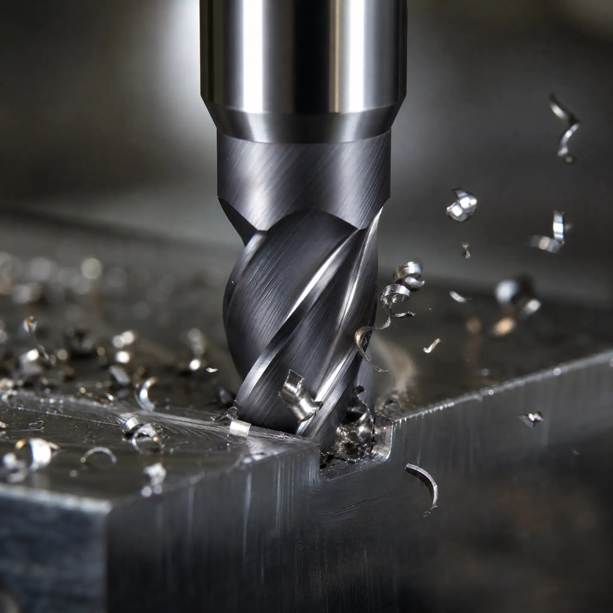
Struggling to balance machining speed with runaway tooling costs and unexpected downtime? You’re likely pushing for faster feed rates, believing it’s the key to efficiency, only to see your production schedule thrown into chaos. The solution lies in understanding that the optimal chip load for a carbide end mill isn't about maximum speed; it's about achieving the lowest total cost and greatest operational stability[1].
The correct chip load for a carbide end mill is the specific thickness of material removed by each cutting edge that balances machining speed against tool life, part quality, and overall process stability. It's not a single number from a catalog, but a strategic parameter adjusted to your specific machine, material, and workholding to achieve the lowest possible cost-per-part.
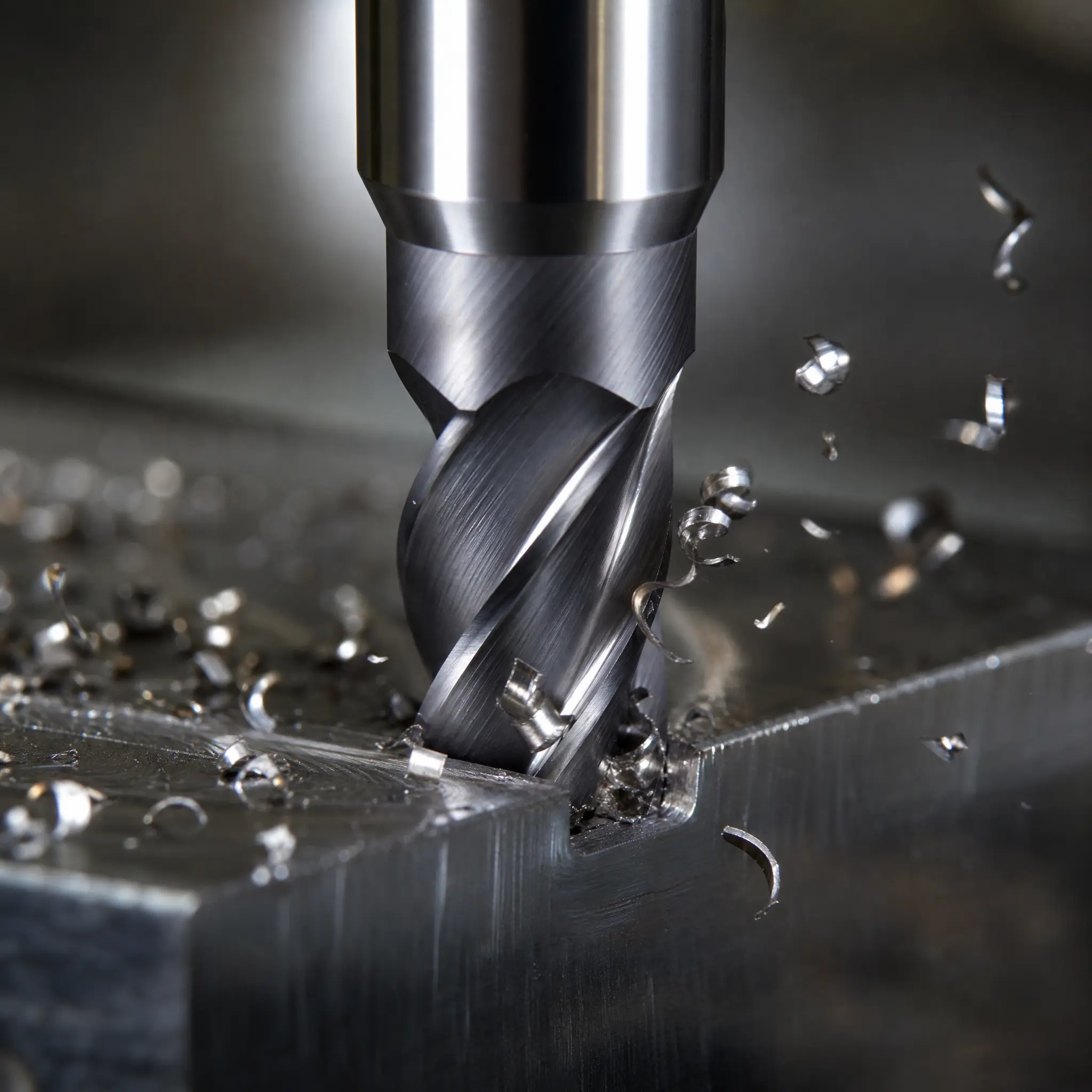
Now that we’ve defined it, let’s explore how this single parameter directly impacts your operational costs. We will uncover why the manufacturer's chart is just the beginning of the story and how you can translate this technical data into real business results.
Why is Focusing Only on Speed a Costly Mistake?
You’ve been told faster is better, and you’ve tasked your team with reducing cycle times. Yet, you're noticing the tooling budget is ballooning and machines are sitting idle more often. Why does this aggressive push for higher feed rates sometimes backfire so spectacularly?
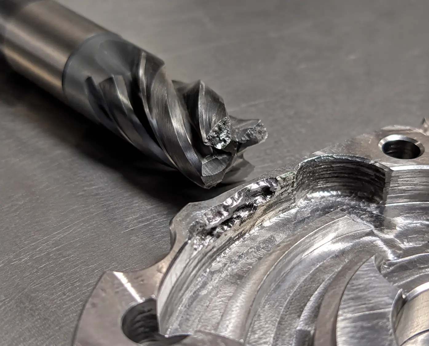
Focusing solely on speed often leads to premature tool wear, catastrophic tool failure, and expensive machine downtime.[2] These hidden costs can easily erase any perceived gains from a shorter cycle time, ultimately increasing your total cost of production.
Dive Deeper: The True Cost of Chasing Cycle Time
In my role as an application engineer, a common scenario I encounter is a shop floor chasing faster cycle times at all costs. A manager sees a potential 15% reduction in cycle time and translates that directly to a 15% increase in output. On paper, it looks like a clear win. In reality, the outcome is often the exact opposite.
When you increase the chip load too aggressively, you dramatically increase the forces on the cutting tool and the amount of heat generated at the cutting edge.[3] Carbide is incredibly hard, but it's also brittle.[4] Excessive force can lead to chipping or immediate fracture. Even if the tool doesn't break outright, the intense heat will accelerate wear, drastically shortening the tool's effective life[5].
The Hidden Costs of an Aggressive Strategy
The pursuit of speed above all else introduces several financial burdens that are often overlooked in a simple cycle time calculation.
- Increased Tool Consumption: The most obvious cost. If a tool that should last for 100 parts now only lasts for 30, you've more than tripled your tooling cost for that job. I've seen shops where a 10% reduction in cycle time led to a 50% increase in their monthly tooling spend.
- Unplanned Machine Downtime[6]: This is, by far, the most expensive consequence. When a carbide end mill fails unexpectedly mid-cut, the machine stops. An operator has to intervene, remove the broken tool, potentially inspect the spindle, replace the tool, touch it off, and restart the program. That's 15-30 minutes of lost production where your multi-hundred-thousand-dollar asset is making no money.
- Scrapped Parts: A tool failure often ruins the part being machined.[7] This means the cost of the raw material is lost, as is all the machine time that was invested up to that point. For high-value materials or complex parts with long prior operations, this can be a devastating financial hit.
- Risk to Equipment: A catastrophic tool failure can do more than just break a tool. The shock can damage expensive tool holders, the workholding fixture, or even the machine's spindle—a repair that can cost tens of thousands of dollars and take a machine out of service for weeks.
The lesson is clear: a 10% reduction in cycle time is a net loss if it results in a 30% increase in tool-related costs and unplanned downtime. True efficiency comes from a predictable, stable process, not a fragile, high-speed one.
Is the Manufacturer's Data Sheet the Final Word on Chip Load for a Carbide End Mill?
You've diligently followed the tool manufacturer's catalog, using their recommended speeds and feeds for the material you're cutting. But you’re still getting inconsistent results—chatter one day, poor finish the next. What’s missing from the equation?
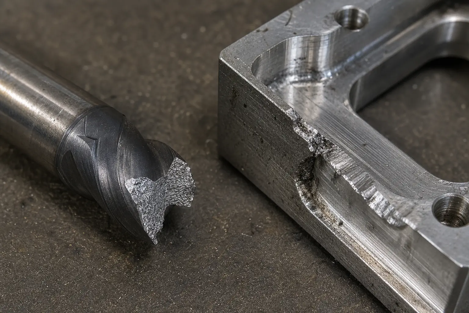
The manufacturer's data is a crucial starting point developed under ideal laboratory conditions. However, it cannot account for your real-world setup. Factors like machine rigidity, spindle health, and workholding stability must be considered[8] to find the true optimal chip load for a carbide end mill in your facility.
Dive Deeper: Beyond the Catalog: Assessing Your Real-World Conditions
A tool catalog provides a scientifically determined baseline. It assumes a brand-new, perfectly rigid machine, a pristine spindle with near-zero runout, and rock-solid workholding. Your shop floor is not a laboratory. True optimization requires treating the machine, the holder, the tool, and the workpiece as a single, interconnected system.
I once visited a shop that was struggling with terrible chatter and breaking tools on a high-volume aluminum job. They were using our tools and were frustrated because they were following our catalog parameters "by the book." The operator was convinced the tools were faulty. After a few minutes of watching the machine run, the problem was obvious. Their workholding fixture was flimsy, and the part was vibrating audibly during the cut.
The "book" parameters were too aggressive for their system. We backed off the chip load by 20% and reduced the depth of cut slightly. The chatter vanished instantly. The cycle time was about 45 seconds longer, but they finished the rest of the 5,000-part run without breaking another tool. They saved a fortune in tooling and eliminated the stress of an unpredictable process.
What to Evaluate in Your Machining System
To adapt the starting parameters to your environment, you need to become a detective and assess these key factors:
- Machine Tool Rigidity: Is the machine 15 years old with worn box ways, or is it a brand-new linear guide machine? Older, less rigid machines will deflect more under cutting forces, requiring a more conservative chip load to prevent vibration (chatter).[9]
- Spindle Health: A spindle with worn bearings will have excessive runout, meaning the tool isn't spinning perfectly on its central axis.[10] This imbalance hammers the cutting edges unevenly, leading to rapid failure. A quick check with a dial indicator can tell you if your spindle is a contributing factor.
- Workholding: How securely is the part held? A high-quality vise, a custom hydraulic fixture, or vacuum chuck provides stability. If the part can move or vibrate even slightly, you must reduce the cutting forces by lowering the chip load.
- Tool Holder: The quality of the connection between the spindle and the tool is critical. A high-precision holder (like a hydraulic or shrink-fit holder) provides better concentricity and balance than a standard, worn-out collet chuck.[11] This stability allows for more aggressive, yet reliable, parameters.
- Tool Stick-out: The farther the end mill protrudes from the holder, the more it will want to deflect and vibrate.[12] A fundamental rule is to use the shortest tool possible for the job. If you must use a long tool, you will need to significantly reduce your chip load and depth of cut.
By honestly assessing your complete system, you can intelligently adjust the catalog recommendations to find a sweet spot that delivers both performance and reliability.
How Can We Translate Technical Parameters into Business Outcomes?
You see charts filled with technical jargon like SFM (Surface Feet per Minute), RPM (Revolutions Per Minute), and IPT (Inches Per Tooth). But as a manager, how do you connect those numbers to your profit and loss statement?
The key is to translate every technical adjustment into its direct financial impact. You should frame changes to the chip load for a carbide end mill not as a simple technical tweak, but as a strategic decision to lower the cost-per-part, improve production predictability, and reduce overall operational risk.

Dive Deeper: Shifting from Cycle Time to Cost-Per-Part
The ultimate goal of any manufacturing operation is not to make parts the fastest, but to make them at the lowest possible total cost while meeting quality and delivery targets. A predictable, stable machining process is a powerful business asset. It allows for accurate job quoting, reliable production scheduling, and confident delivery promises to your customers. An unstable process, even if it's occasionally faster, erodes profit and damages your reputation.
The most effective way to illustrate this is to shift the focus from cycle time to cost-per-part. Let's compare two strategies for the same job.
Strategy Comparison: Aggressive vs. Balanced
Metric | Aggressive Strategy (High Chip Load) | Balanced Strategy (Optimized Chip Load) |
|---|---|---|
Cycle Time per Part | 2 minutes | 2.2 minutes (10% slower) |
Tool Life per End Mill | 50 parts | 150 parts |
Tool Cost (assume $30/tool) | $30 | $30 |
Tool Cost per Part | $0.60 | $0.20 |
Risk of Downtime/Scrap | High | Low |
Overall Profitability | Lower | Higher |
As the table clearly shows, the "Balanced Strategy" is slightly slower on a per-part basis. A manager focused only on cycle time would reject it. However, it is three times more efficient in terms of tooling cost.
More importantly, the low risk of downtime means production is predictable. You can confidently schedule the next job, order material with certainty, and promise a delivery date. With the "Aggressive Strategy," you are constantly gambling. You might finish a run of 50 parts ahead of schedule, but you might also spend an hour of that "saved" time dealing with a broken tool and a scrapped part, erasing all gains and then some.
This is how you connect technical parameters to business outcomes. Every conversation about speeds and feeds should ultimately lead to a discussion about stability, risk management, and total cost. By embracing a balanced approach, you build a more resilient and profitable operation.
Frequently Asked Questions
What is the first sign of an incorrect chip load?
The most common first sign is an unusual sound, such as a high-pitched squeal (chip load too low) or a low-frequency rumbling known as chatter (chip load too high for the system's rigidity). Other immediate signs include a poor surface finish on the part or visible, premature discoloration and wear on the end mill's cutting edges.
Does material type affect the ideal chip load for a carbide end mill?
Absolutely. The ideal chip load is heavily dependent on the material being machined. Softer materials like aluminum can handle a much higher chip load than hard, tough, or abrasive materials like stainless steel, titanium, or Inconel. For harder materials, a more conservative chip load is necessary to manage cutting forces and prevent excessive heat buildup.
How does the number of flutes on an end mill affect chip load?
Chip load is calculated per tooth (or per flute). To maintain the same chip thickness per tooth, you must increase the machine's overall feed rate (IPM) as you increase the number of flutes. For example, a 6-flute end mill must be fed twice as fast as a 3-flute end mill to achieve the same chip load.
Can a chip load be too low?
Yes, and it can be just as damaging as a chip load that is too high. When the chip load is too low, the cutting edges don't get "under" the material to form a proper chip. Instead, they rub or burnish the surface. This creates excessive friction and heat, which can cause work-hardening of the material and will rapidly dull the tool's cutting edge.
Conclusion
Ultimately, mastering the chip load for a carbide end mill is a critical exercise in risk management and cost control. The right approach moves beyond chasing the highest possible speed and instead focuses on creating a predictable, stable, and profitable manufacturing process. Remember that the manufacturer's data sheet is your starting point, not the final destination. The true optimal parameters are found by carefully evaluating your entire machining system—from the machine's condition to the workholding—and making data-driven decisions that prioritize the lowest cost-per-part. This balanced strategy is the key to turning your machining operations into a reliable competitive advantage.
At QT TOOLS, we partner with our customers to find this balance. Our experience isn't just in making high-quality tools; it's in applying them effectively in real-world conditions. If you're ready to move beyond the catalog and achieve a truly predictable, low-cost process, our team is here to help. Contact us today for a consultation to evaluate your application and build a tooling strategy that works for your bottom line.
1
"Optimizing economics of machining for LM25Al/VC composite material ...", https://pmc.ncbi.nlm.nih.gov/articles/PMC11937586/. University manufacturing-engineering materials on machining economics support that feed, speed, and chip load decisions are evaluated against tool life, production rate, and cost per part, rather than by maximum cutting speed alone. Evidence role: general_support; source type: education. Supports: Machining texts and university materials explain that cutting parameters are optimized by considering material removal rate, tool life, part quality, and cost rather than speed alone.. Scope note: The source would provide general support for machining-parameter optimization, not proof of the specific cost outcome in any individual shop.
2
"Comparison of Tool Wear, Surface Roughness, Cutting Forces ...", https://pmc.ncbi.nlm.nih.gov/articles/PMC10303288/. Peer-reviewed machining studies support that cutting speed, feed, and chip thickness affect cutting forces, tool wear, and tool failure risk, which can reduce process reliability and contribute to downtime. Evidence role: general_support; source type: paper. Supports: Research on milling and tool wear shows that cutting parameters influence wear rate, failure risk, and process reliability.. Scope note: Such studies typically demonstrate technical mechanisms and experimental wear outcomes, not the exact downtime cost for a specific facility.
3
"Understanding the Relationship between Surface Quality and Chip ...", https://pmc.ncbi.nlm.nih.gov/articles/PMC11050977/. Experimental milling research supports that higher feed per tooth increases uncut chip thickness and is associated with higher cutting forces and thermal loading at the tool-workpiece interface. Evidence role: mechanism; source type: paper. Supports: Experimental and analytical milling research shows that increasing feed per tooth or uncut chip thickness generally increases cutting force and affects cutting temperature.. Scope note: The magnitude of force and temperature change depends on tool geometry, material, coolant, speed, and engagement conditions.
4
"Tungsten carbide", https://en.wikipedia.org/wiki/Tungsten_carbide. Reference materials on cemented carbides support that carbide cutting-tool materials are valued for high hardness and wear resistance but have limited toughness and can fail by brittle fracture. Evidence role: definition; source type: encyclopedia. Supports: Reference sources describe cemented carbide or tungsten carbide as a hard, wear-resistant material with brittle fracture behavior compared with tougher tool materials.. Scope note: The source would describe general material properties, not the fracture behavior of every carbide grade or coating.
5
"The study on the effect of various tool wear indicators on the machining ...", https://www.sciencedirect.com/science/article/pii/S2238785424005386. Peer-reviewed machining literature supports that elevated cutting temperatures contribute to accelerated tool-wear mechanisms and can shorten effective tool life. Evidence role: mechanism; source type: paper. Supports: Machining research identifies elevated cutting temperature as a contributor to wear mechanisms such as diffusion, oxidation, adhesion, and crater or flank wear.. Scope note: The exact reduction in tool life depends on the work material, carbide grade, coating, coolant, and cutting parameters.
6
"Maintenance Costs and Advanced Maintenance Techniques in ...", https://www.nist.gov/publications/maintenance-costs-and-advanced-maintenance-techniques-manufacturing-machinery-survey. Government manufacturing studies support that unplanned equipment downtime can impose substantial costs through lost production time, labor intervention, and maintenance activity. Evidence role: statistic; source type: government. Supports: Government or institutional manufacturing studies document that unplanned downtime imposes significant production and maintenance costs.. Scope note: General downtime estimates may not isolate carbide end mill failures specifically and may vary widely by industry and machine utilization.
7
"Effect of Cutting Conditions on Roughness and Cutting Force ...", https://pmc.ncbi.nlm.nih.gov/articles/PMC12985697/. Research on tool-condition monitoring supports that cutting-tool breakage and severe wear are associated with degraded surface integrity, dimensional error, and potential rejection of machined parts. Evidence role: general_support; source type: research. Supports: Manufacturing research on tool condition monitoring and tool failure explains that tool breakage or severe wear can cause dimensional errors, surface damage, and rejected parts.. Scope note: The source would support the general risk of scrap, while the probability and cost depend on part geometry, operation stage, and inspection standards.
8
"machine learning for stability analysis of milling process", https://voljournals.utk.edu/utk_gradthes/11785/. Manufacturing-engineering teaching materials support that milling stability and allowable cutting parameters depend on the stiffness and dynamic behavior of the machine-tool-fixture-workpiece system. Evidence role: expert_consensus; source type: education. Supports: Manufacturing engineering sources explain that stable milling depends on the combined stiffness and condition of the machine tool, spindle, holder, fixture, and workpiece.. Scope note: The source would support the general systems principle, not provide a direct chip-load value for a specific machine.
9
"Chatter Stability of Machining Operations Dedicated to S.A. Tobias ...", https://academy.cba.mit.edu/classes/computer_machining/chatter.pdf. Machining-dynamics literature supports that reduced structural stiffness increases tool-workpiece deflection and susceptibility to chatter, which constrains stable feed and engagement choices. Evidence role: mechanism; source type: paper. Supports: Research on machining dynamics links tool-machine stiffness and cutting forces to deflection, regenerative chatter, and stable parameter selection.. Scope note: Age alone is only an indirect indicator of rigidity; actual stiffness and chatter behavior require measurement or stability analysis.
10
"Runout effects in milling: Surface finish, surface location error, and stability", https://mtrc.utk.edu/wp-content/uploads/sites/45/2019/09/runout_ra_sle_stability.pdf. Machine-tool condition-monitoring literature supports that spindle-bearing degradation can increase vibration and runout, reducing rotational accuracy at the cutting tool. Evidence role: mechanism; source type: research. Supports: Machine-tool condition-monitoring sources describe bearing wear as a cause of increased vibration, runout, and spindle accuracy degradation.. Scope note: Runout may also arise from holder, collet, tool shank, contamination, or assembly errors, so bearing wear is not the only possible cause.
11
"Advantages of Hydraulic Chucks Over Shrink-Fit Tool ...", https://www.bigdaishowa.com/en/blog/advantages-hydraulic-chucks-over-shrink-fit-tool-holders. Research on tool-holder runout supports that improved concentricity and balance reduce uneven cutting-edge loading and can improve milling stability and tool life. Evidence role: general_support; source type: paper. Supports: Machining studies show that tool-holder runout and imbalance affect cutting-edge loading, surface finish, vibration, and tool life, and that high-precision holders are designed to reduce these errors.. Scope note: The source may not rank every hydraulic, shrink-fit, or collet-holder design; holder condition and setup quality remain important.
12
"End mill length / stickout effects on DOC", https://www.practicalmachinist.com/forum/threads/end-mill-length-stickout-effects-on-doc.229798/. Engineering mechanics and machining-stability sources support that a longer tool overhang behaves like a less stiff cantilever, increasing deflection and vibration susceptibility during milling. Evidence role: mechanism; source type: education. Supports: Engineering and machining sources explain that increasing tool overhang reduces stiffness and increases deflection, raising vibration and chatter risk.. Scope note: The exact amount of deflection also depends on tool diameter, flute geometry, material, holder stiffness, and cutting-force magnitude.