
Sep 19, 2026Technical Blog & Machining Tips
How Do You Choose the Right High Feed Carbide End Mill?
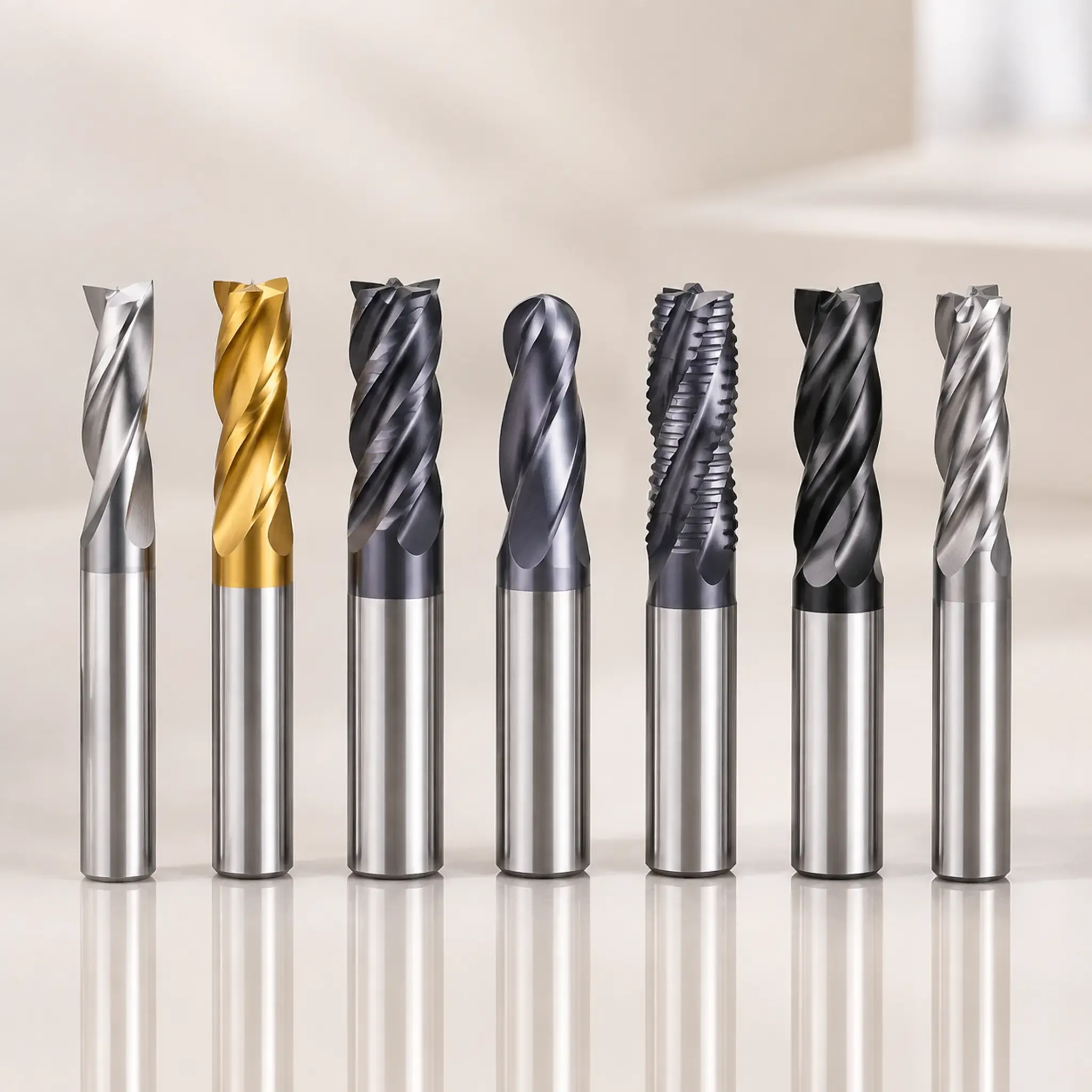
Are you struggling to get the promised speed and efficiency from your milling operations? You've invested in advanced tools, but you're still seeing inconsistent tool life, poor surface finishes, or even catastrophic failures that bring production to a halt. The solution isn't just a better tool; it's a better selection process for your high feed carbide end mill that starts with your specific material.
Choosing the right high feed carbide end mill is not about finding a single "best" tool. Instead, it is a calculated trade-off between machining speed, tool life, and risk. The optimal choice is determined primarily by the specific material you are machining, which dictates the necessary tool geometry, coating, and cutting parameters.[1]
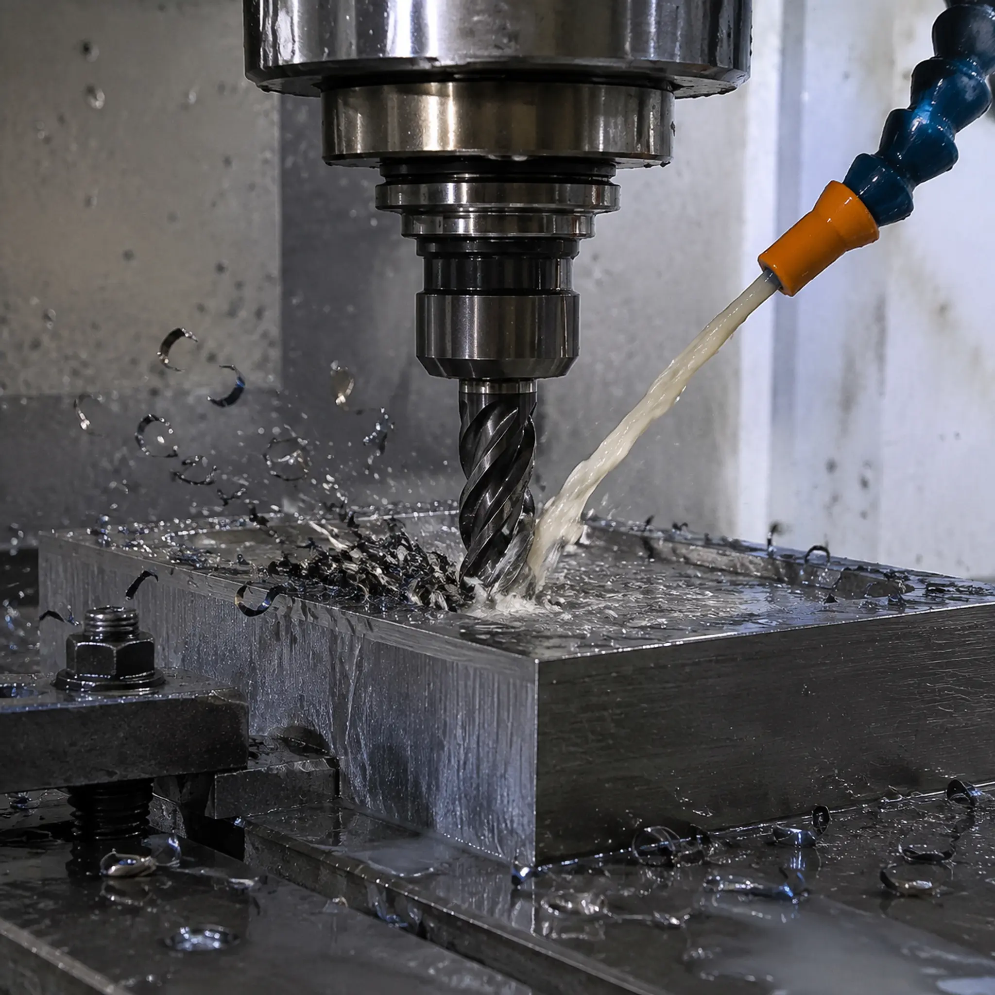
This fundamental shift in thinking—from searching for a universal "best" to making a specific, calculated choice—is the key to unlocking true high feed performance. Let's explore how to make that choice by looking at your material, your machining system, and the right questions to ask.
Why Does Your Material Determine the Right High Feed Carbide End Mill?
Many machinists look at a catalog and get overwhelmed by options, trying to find the one tool that does it all. This often leads to choosing a general-purpose tool that performs sub-optimally everywhere. Is there a better way to start the selection process?
The most common mistake is seeking a single "best" tool. The correct approach begins by answering the question, "What material am I machining?" This single factor has the largest impact on the ideal geometry, coating, and parameters for your high feed carbide end mill.
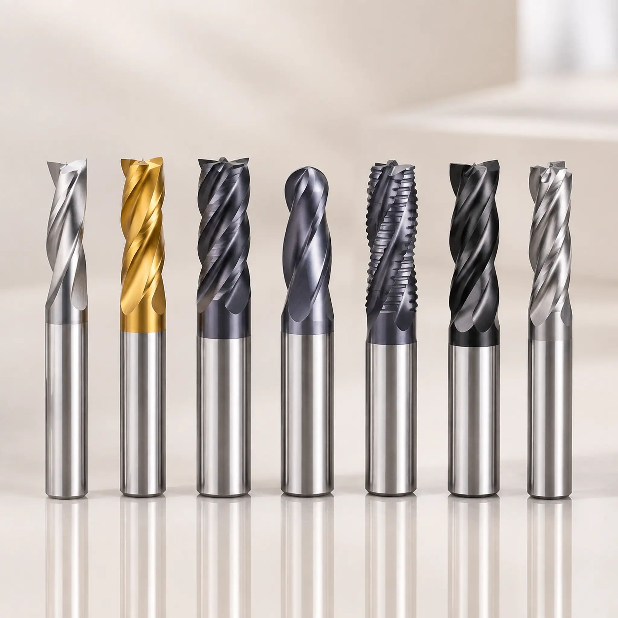
When a customer asks me for a high feed carbide end mill, my first question is always about their material. This isn't just a detail; it's the foundation of the entire recommendation. The properties of the workpiece—its hardness, abrasiveness, and thermal conductivity—dictate how the tool must be designed to survive and perform efficiently. A tool designed for free-machining aluminum would be destroyed in seconds if applied to hardened D2 tool steel with the same parameters.[2]
H3: Geometry for Different Material Groups
The unique shape of a high feed end mill, with its large corner radius and shallow axial depth of cut, is designed to achieve radial chip thinning. This allows for extremely high feed rates by directing cutting forces axially up into the spindle, promoting stability.[3] However, subtle changes in this geometry have massive implications for different materials.
- Soft Steels and Aluminum (Under 45 HRC): For these materials, we often recommend tools with sharper cutting edges and more positive rake angles. This helps shear the material cleanly, reducing built-up edge (BUE) and improving chip evacuation.[4] The flute pockets can be larger and more polished to prevent chips from sticking.
- Hardened Steels and Tool Steels (45-65 HRC): Machining hard materials generates immense heat and pressure at the cutting edge. Here, we need a high feed carbide end mill with a more robust geometry. This often includes a negative rake angle and a honed or chamfered cutting edge (an edge preparation) to add strength and prevent microscopic chipping[5], which is the precursor to catastrophic failure.
- Stainless Steels and Superalloys (Inconel, Titanium): These materials are notoriously difficult to machine due to their work-hardening properties and poor thermal conductivity.[6] Heat doesn't escape with the chip; it soaks into the tool. For these applications, we need tools with optimized helix angles and special edge preparations that are sharp enough to shear the material without causing excessive work hardening, yet strong enough to resist the high cutting forces.
H3: The Role of Coatings
If geometry is the skeleton, the coating is the armor. A PVD (Physical Vapor Deposition) coating is a micro-thin layer of ceramic material that dramatically enhances a tool's performance[7], but only if it's the right one for the job.
Coating Type | Primary Application | Key Benefit |
|---|---|---|
TiN (Titanium Nitride) | General Purpose, Non-Ferrous | Good lubricity, wear indicator (gold color) |
TiCN (Titanium Carbonitride) | Abrasive Materials, Low/Med Steels | Increased hardness and wear resistance over TiN |
TiAlN (Titanium Aluminum Nitride) | Hardened Steels, High-Temp Alloys | |
AlCrN (Aluminum Chromium Nitride) | High-Speed Machining of Steels | Excellent hot hardness and oxidation resistance |
Simply choosing a tool with a "good" coating isn't enough. For example, using a standard TiAlN coating in aluminum can lead to chemical reactions and built-up edge. In contrast, that same coating is essential for creating a thermal barrier when machining hardened steel. The material dictates the coating.
Is Your High Feed Carbide End Mill Just One Part of a Larger System?
You've selected the perfect material-specific tool, but your results are still disappointing. You're experiencing chatter, poor tool life, or an inability to reach the supplier's recommended feed rates. What's going wrong?
You may be forgetting that high feed milling is a system. The high feed carbide end mill is a critical component, but its success is entirely dependent on the machine's capability, the tool holder's rigidity, and the CAM programming strategy. A mismatch in any one area will negate all benefits.
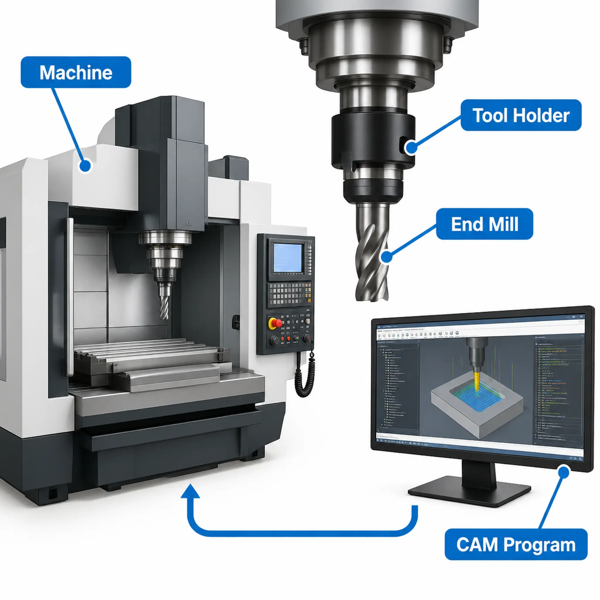
I once worked with a shop that purchased a top-of-the-line high feed carbide end mill for a tough roughing job in 316 stainless steel. They were breaking tools constantly. After a quick discussion, we found the issue: they were holding the tool in an old, worn-out side-lock holder. The tool was fine, but the lack of rigidity and high runout in the holder created an unstable system that doomed the process from the start. They switched to a high-quality hydraulic or shrink-fit holder, and the problem vanished.
H3: Machine and Spindle Capability
High feed milling directs cutting forces axially. This is great for stability, but it means your machine's spindle bearings must be able to handle that axial load. Older or lighter-duty machines may struggle. Furthermore, the control is critical. The machine must be able to process the CAM program's code fast enough to maintain the programmed feed rate through complex toolpaths without stuttering. A machine that can't "look ahead" in the code will cause dwells that lead to tool damage.
H3: The Unsung Hero: The Tool Holder
The tool holder is the crucial link between the machine spindle and the cutting tool. Its importance cannot be overstated in high feed applications.
- Rigidity: The holder must securely grip the end mill with minimal deflection. Any movement here translates to chatter and unpredictable cutting action.
- Balance: At the high RPMs often used, an unbalanced holder will create vibrations that destroy surface finish and shatter carbide.
- Runout: Total Indicated Runout (TIR) is the measure of how much the tool "wobbles." High runout means only one flute is doing the majority of the work, leading to premature wear and failure.[9] For high feed milling, aim for a runout of 0.0004" (10 µm) or less.[10]
Holder Type | Rigidity | Runout | Best Use Case |
|---|---|---|---|
ER Collet Chuck | Good | Good | General purpose, versatile |
Side Lock / Weldon | Good | Poor | High pull-out resistance, but poor runout |
Milling Chuck | Excellent | Good | High-grip, good for heavy roughing |
Shrink-Fit | Excellent | Excellent | Best for high-speed, high-precision work |
Hydraulic Chuck | Excellent | Excellent | Excellent vibration damping and grip |
For any serious high feed carbide end mill application, I strongly recommend investing in high-quality milling, shrink-fit, or hydraulic chucks.
H3: CAM Programming Strategy
The toolpath itself is the final piece of the puzzle. Abrupt changes in direction, plunging directly into material, and sharp corners are killers. Modern CAM software offers specialized high feed toolpaths that are essential for success. These strategies use smooth, arcing motions, trochoidal milling, and controlled engagement to maintain a constant chip load on the tool, which is the key to both speed and tool life.[11]
How Do You Manage Risk When Selecting a High Feed Carbide End Mill?
You understand the importance of material and the system. But when you're pushing a machine at 400 inches per minute, things can go wrong fast. How do you approach tool selection as a form of risk management?
Choosing a high feed carbide end mill is not just about maximizing performance; it's about minimizing risk. The primary risk of a poor selection is not just slower performance, but catastrophic tool failure, a scrapped workpiece worth thousands of dollars, or even damage to the machine spindle.
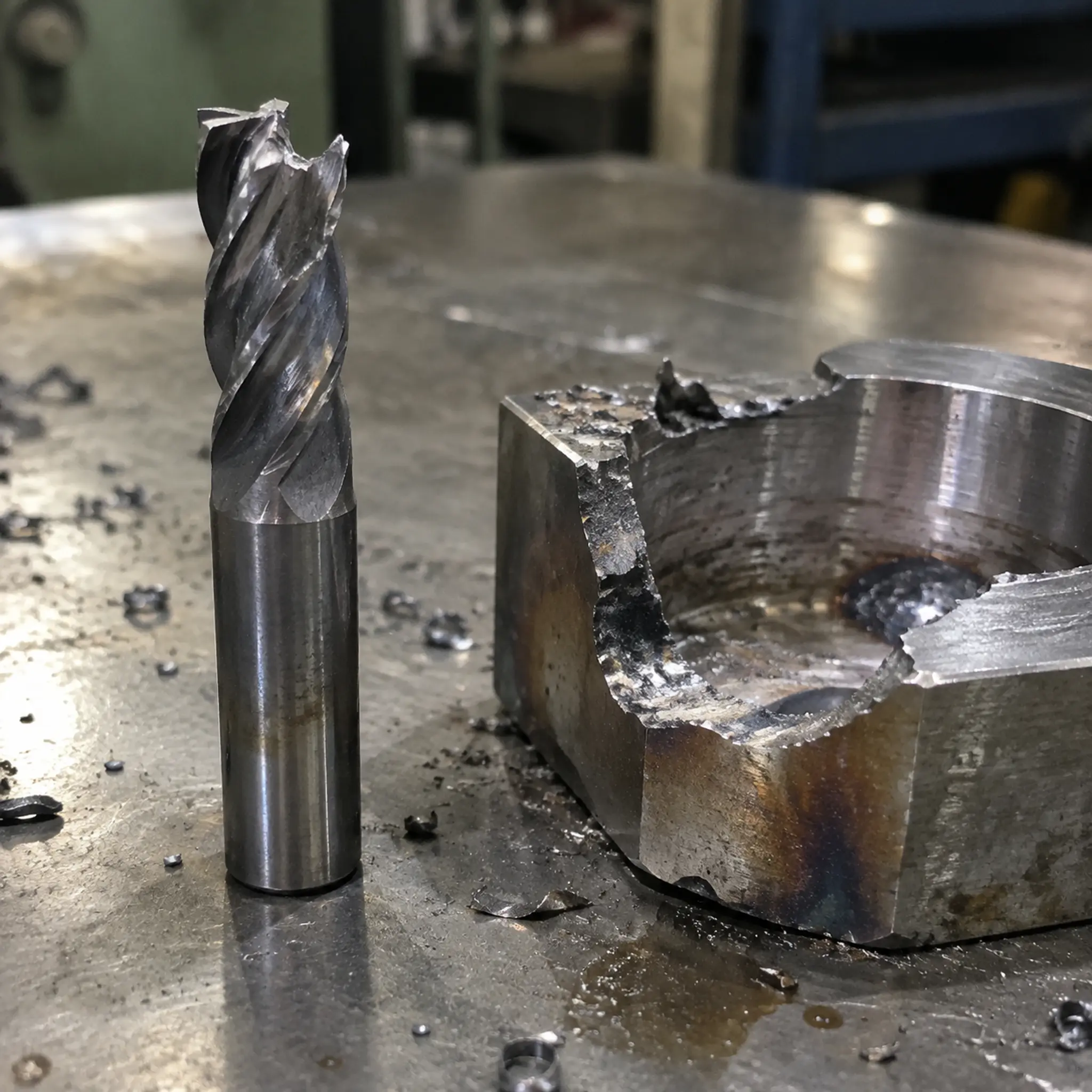
Framing the selection process as a risk management activity forces you to consider the consequences of failure. It shifts the focus from "How fast can this go?" to "How reliably can I run this process?" Reliability is where the real profit is found.
H3: Understanding Failure Modes
When a high feed carbide end mill fails, it's trying to tell you something. Understanding why it failed is the key to preventing it from happening again.
- Chipping/Fracture: This is often a sign of instability. The cause could be a lack of rigidity in the setup (tool holder, workpiece clamping), excessive runout, or a tool geometry that is too sharp and fragile for the material being cut.
- Abrasive Wear / Flank Wear: This is a normal, gradual wear process. If it happens too quickly, it could mean your cutting speed is too high, the tool coating isn't suitable for the material's abrasiveness, or you have insufficient coolant.
- Thermal Cracking / Heat Damage: If the tool turns blue or shows signs of cracking, it's a clear indicator of excessive heat. This is common in materials like stainless steel or Inconel. The solution might be a more heat-resistant coating (like AlCrN), reducing the cutting speed, or improving coolant application.
- Built-Up Edge (BUE): This happens when workpiece material welds itself to the cutting edge, common in aluminum and some stainless steels. It's often caused by cutting speeds being too low or using a tool without a high-lubricity coating.
H3: Starting with Conservative Parameters
Every tool supplier provides a chart of recommended speeds and feeds. These are an excellent starting point, but they are not the law. They represent an ideal scenario. My advice is always to start conservatively.
- Begin at the low end of the recommended surface footage (SFM) for your material.
- Start at 50-75% of the recommended feed per tooth (FPT).
- Run a short test cut and listen to the machine. Does it sound stable? Is it vibrating?
- Inspect the tool and the chip. A good chip is a sign of a healthy process. For high feed milling, chips should be thin and light. A thick, heavy chip means your axial depth of cut might be too large for your radial stepover, negating the chip thinning effect.
- Gradually increase the feed rate in small increments (10-15%) until you reach the supplier's recommendation or hear signs of instability.
This methodical approach minimizes the risk of a sudden failure and allows you to find the "sweet spot" for your specific machine, holder, and workpiece setup.
What Should You Ask Your Supplier About Their High Feed Carbide End Mill?
You're ready to engage with a supplier, but you want to move beyond the marketing copy. You need actionable information to make an informed decision. What specific questions will get you the answers you need?
Instead of just comparing technical data sheets, you should ask targeted questions that force the supplier to demonstrate their application expertise. The most crucial question is: "What are the recommended parameters and limitations of this high feed carbide end mill for machining [my specific material], and can you provide a case study?"
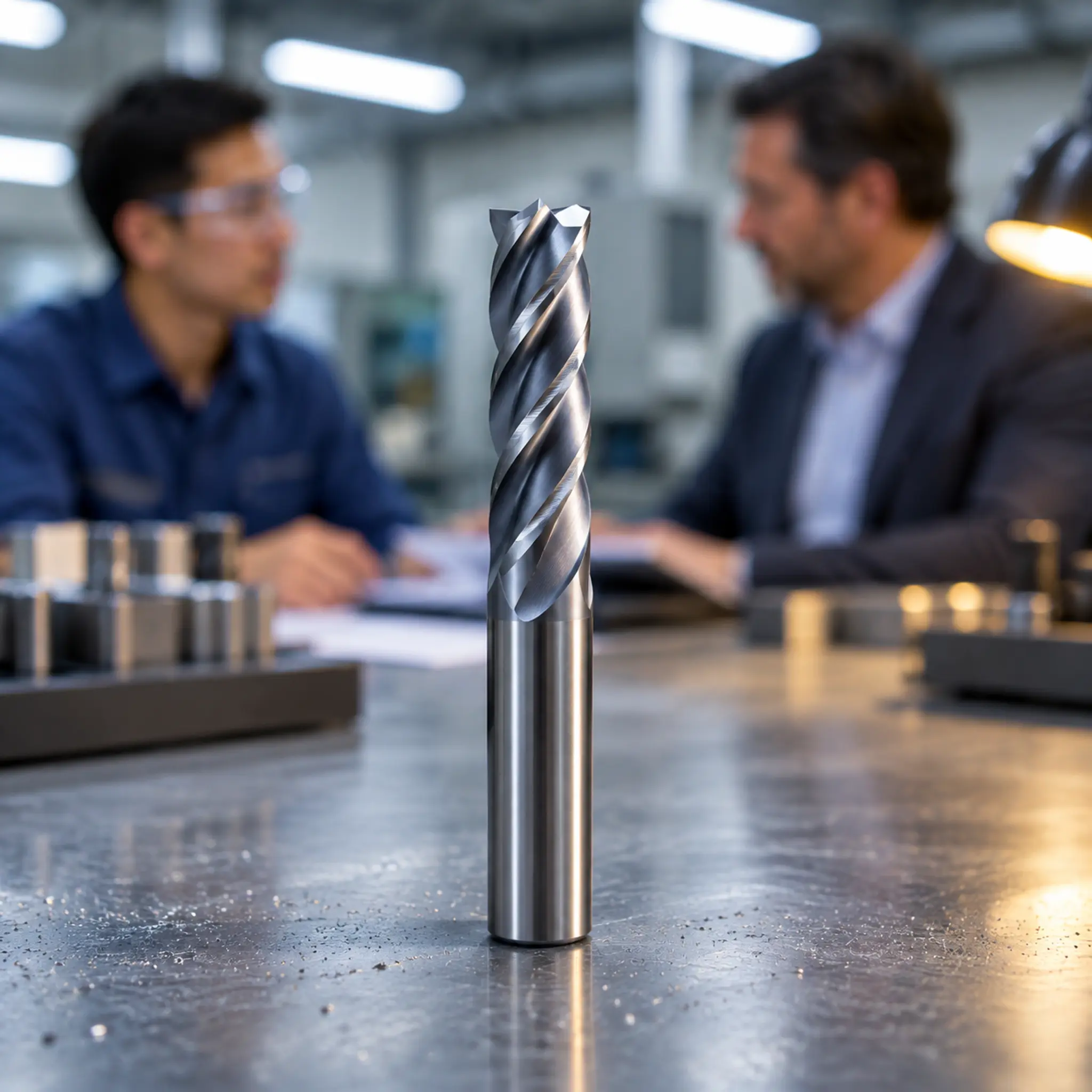
As a tool manufacturer, this is the question I want customers to ask. It shows they are serious about process optimization, and it allows us to become a true partner rather than just a vendor. A good supplier should be able to answer this question in detail. If they can't, it's a major red flag.
H3: A Checklist of Questions for Your Supplier
When you contact us or any other supplier, come prepared with specifics. The more information you provide, the better the recommendation we can give.
Information to Provide Your Supplier:
- Workpiece Material: Be specific (e.g., "4140 pre-hardened to 32 HRC," not just "steel").
- Machine: Make, model, and age. Is it a 50-taper beast or a 30-taper high-speed machine?
- Tool Holder: What type of holder will you be using?
- The Operation: Is it pocketing, slotting, or face milling? What is the maximum axial depth of cut (ADOC) and radial width of cut (RDOC)?
- Your Goal: Are you trying to reduce cycle time, increase tool life, or improve surface finish?
Questions to Ask Your Supplier:
- Application-Specific Parameters: Based on my material and machine, what is your recommended starting SFM, FPT, ADOC, and RDOC for this high feed carbide end mill?
- Expected Limitations: What are the signs that I'm pushing this tool too hard? What is the most common failure mode for this tool in my application, and how do I avoid it?
- Case Studies or Test Data: Can you provide any data or examples of this tool being used successfully in a similar application? This demonstrates real-world validation, not just theoretical performance.
- Geometry and Coating Rationale: Why did you choose this specific geometry (rake angle, edge prep) and coating for this tool? How does it benefit my specific material?
- System Requirements: What are the minimum requirements for the tool holder and machine rigidity to make this tool perform as advertised?
A supplier who can confidently and transparently answer these questions is one who understands that selling a high feed carbide end mill is about providing a complete solution.
Frequently Asked Questions
What is the main difference between high feed milling and high efficiency milling (HEM)?
High feed milling uses a very shallow axial depth of cut (ADOC) and a large radial width of cut (RDOC) with an extremely high feed rate. It excels at rapid bulk material removal. High efficiency milling (HEM) uses a deep ADOC but a very small RDOC, often using more of the flute length at high speeds.
Can I use a high feed carbide end mill on a less rigid machine?
While not ideal, it's often more successful than using a conventional end mill. Because high feed milling directs forces axially into the spindle, it can be more stable on lighter machines than traditional milling, which exerts heavy radial pressure. However, you will need to use more conservative parameters.
Why are my chips thick and blue when using a high feed tool?
This is a classic sign that the "chip thinning" effect is not occurring correctly. It likely means your axial depth of cut is too great for the tool's geometry, or your feed rate is too low for the programmed depth. The tool is behaving like a conventional end mill, leading to excessive heat and thick chips. Reduce your ADOC significantly and re-test.
How does coolant affect high feed milling performance?
For many materials like hardened steels, running a high feed carbide end mill dry with an air blast is often preferred. The high heat generated is managed by the tool's coating, and an air blast effectively clears chips. Introducing liquid coolant can cause thermal shock to the hot carbide, leading to micro-cracks and premature failure.[12] For materials like titanium or aluminum, coolant may be necessary to prevent work-hardening or chip welding.
Conclusion
Choosing the right high feed carbide end mill is a strategic decision, not just a purchase. It requires moving beyond a search for the "best" tool and adopting a systematic process. By putting your material first, you can narrow down the choices for geometry and coating. By viewing the tool as part of a holistic system—including the machine, holder, and CAM program— you can create a stable and predictable process. Finally, by treating selection as a risk management activity and asking suppliers the right questions, you transform a simple transaction into a partnership for productivity. This methodical approach is the most reliable path to unlocking the incredible metal removal rates that a high feed carbide end mill promises.
At QT TOOLS, we believe in partnering with our customers. If you're looking to optimize your milling operations, we're ready to help you select the right tool for your specific application. Contact us today to discuss your material and your goals.
1
"[PDF] Effects of machining parameters and cooling strategies on cutting ...", https://scholarsmine.mst.edu/cgi/viewcontent.cgi?article=9044&context=masters_theses. A university or machining-handbook source explains that workpiece hardness, ductility, abrasiveness, and thermal behavior are standard inputs for selecting milling-tool geometry, coatings, and cutting conditions. Evidence role: general_support; source type: education. Supports: Workpiece material properties are used to select cutting-tool geometry, coatings, and speed/feed parameters in milling.. Scope note: This would support the general selection principle rather than proving that material is always the single most important factor in every high-feed milling setup.
2
"(PDF) Micromilling of Hardened AISI D2 Tool Steel - Academia.edu", https://www.academia.edu/3518777/Micromilling_of_Hardened_AISI_D2_Tool_Steel. A materials or manufacturing reference identifies hardened D2 tool steel as a high-hardness, wear-resistant material requiring conservative cutting conditions compared with aluminum alloys. Evidence role: general_support; source type: education. Supports: Hardened D2 tool steel requires substantially different tooling and cutting parameters than free-machining aluminum.. Scope note: Such a source would contextualize the risk of rapid failure but may not directly verify failure within seconds for the exact tool and parameters described.
3
"Percentage Ratios of Cutting Forces during High-Reed Face ...", https://pmc.ncbi.nlm.nih.gov/articles/PMC9821856/. A peer-reviewed machining study describes high-feed milling as relying on chip-thinning mechanics and cutter geometry that can shift a larger portion of the cutting load toward the tool axis. Evidence role: mechanism; source type: paper. Supports: High-feed milling uses small depths of cut and tool geometry to reduce chip thickness and alter cutting-force directions, enabling higher programmed feed rates.. Scope note: The exact force direction and stability benefit depend on cutter design, engagement, machine structure, and workpiece material.
4
"[PDF] Metal Cutting Physics", https://ocw.mit.edu/courses/2-670-mechanical-engineering-tools-january-iap-2004/15f579e0daa03aff44cd6c557e369377_physics.pdf. A manufacturing-engineering text explains that positive rake angles lower cutting forces and promote shearing chip formation, conditions associated with reduced built-up edge in suitable ductile materials. Evidence role: mechanism; source type: education. Supports: Positive rake geometry reduces cutting resistance and can improve chip formation in ductile or softer materials.. Scope note: Built-up edge also depends on speed, temperature, coating, lubrication, and alloy chemistry, so rake angle alone is not a complete explanation.
5
"Machinability Study of Hardened 1045 Steel When Milling with ...", https://pmc.ncbi.nlm.nih.gov/articles/PMC6926532/. A cutting-tool research paper reports that edge preparation and robust rake geometry influence cutting-edge strength and chipping resistance during machining of hard materials. Evidence role: mechanism; source type: paper. Supports: Edge honing, chamfering, and less-positive or negative rake geometries can increase cutting-edge robustness in hard machining.. Scope note: The optimal edge preparation varies by carbide grade, coating, workpiece hardness, and cutting conditions.
6
"Section 5. Laser/Plasma Assisted Machining - AML", http://aml.engineering.columbia.edu/ntm/CrossProcess/CrossProcessSect5.htm. A review article on difficult-to-machine alloys identifies work hardening and low thermal conductivity as major contributors to machining difficulty in stainless steels, titanium alloys, and nickel-based superalloys. Evidence role: general_support; source type: paper. Supports: Stainless steels, titanium alloys, and nickel-based superalloys are commonly classified as difficult-to-machine materials because of work hardening, heat retention, or low thermal conductivity.. Scope note: The severity of these effects differs among specific grades such as 316 stainless steel, Ti-6Al-4V, and Inconel 718.
7
"Characterization and Evaluation of Engineered Coating ... - PMC", https://pmc.ncbi.nlm.nih.gov/articles/PMC9415707/. A review of PVD hard coatings for cutting tools describes them as thin deposited ceramic or ceramic-like layers that improve wear resistance and tool performance in appropriate machining applications. Evidence role: definition; source type: paper. Supports: PVD coatings are thin hard coatings used on cutting tools to improve wear resistance and performance under suitable conditions.. Scope note: Performance gains depend on matching the coating system to the workpiece material and cutting environment.
8
"The Oxidation Behaviour and Notch Wear Formation of TiAlN ...", https://pmc.ncbi.nlm.nih.gov/articles/PMC8048706/. A coating-science study reports that TiAlN coatings can form alumina-rich oxide layers during high-temperature exposure, which contributes to oxidation resistance in cutting-tool applications. Evidence role: mechanism; source type: paper. Supports: TiAlN coatings can develop protective alumina-rich oxide scales at elevated temperatures, contributing to oxidation resistance.. Scope note: The protective effect depends on coating composition, deposition process, temperature, and cutting environment.
9
"Runout effects in milling: Surface finish, surface location ...", https://mtrc.utk.edu/wp-content/uploads/sites/45/2019/09/runout_ra_sle_stability.pdf. A study of end-milling runout shows that eccentricity produces unequal tooth engagement and uneven cutting loads, conditions associated with accelerated localized tool wear. Evidence role: mechanism; source type: paper. Supports: Runout in milling produces unequal chip loads among teeth, increasing local cutting forces and wear on the most engaged flute.. Scope note: The degree of wear acceleration depends on runout magnitude, cutter diameter, number of flutes, feed per tooth, and material.
10
"Tool Runout - In the Loupe Machinist Blog", https://www.harveyperformance.com/in-the-loupe/tag/tool-runout/. A machining research or metrology source indicates that micrometer-scale tool runout affects tooth loading, surface quality, and tool life in milling operations. Evidence role: general_support; source type: research. Supports: Low runout on the order of micrometers is important for uniform tooth loading and tool life in precision or high-speed milling.. Scope note: A neutral source may support the importance of low runout without endorsing exactly 0.0004 inch as a universal high-feed milling limit.
11
"Investigation of Tool Wear and Chip Morphology in Dry ... - PMC", https://pmc.ncbi.nlm.nih.gov/articles/PMC6630620/. A study of trochoidal or constant-engagement milling reports that smooth toolpaths and controlled radial engagement reduce force variation and can improve tool wear behavior and productivity. Evidence role: mechanism; source type: paper. Supports: Trochoidal and constant-engagement milling strategies can stabilize chip load and cutting forces, supporting higher productivity and tool life under suitable conditions.. Scope note: Benefits depend on programming parameters, machine acceleration limits, cutter geometry, and workpiece material.
12
"Maximizing Tool Life: Understanding Heat and Coolant in ...", https://www.techmet-carbide.com/blog/118/maximizing-tool-life-understanding-heat-and-coolant-in-machining?srsltid=AU7gw4UTrS5ByPPCPyhox828zMMrmtVLHwpZsMsW97WIPn096h7xCout. A cutting-tool wear study explains that rapid thermal cycling during interrupted machining, including coolant-induced temperature changes, can promote thermal cracking in carbide cutting tools. Evidence role: mechanism; source type: paper. Supports: Thermal cycling from coolant in interrupted cutting can contribute to thermal cracking of carbide tools.. Scope note: Coolant effects vary by material, tool coating, coolant delivery method, and whether the process is continuous or interrupted.