
Jul 14, 2026Case Studies & Applications
Are You Just Guessing Your Carbide End Mill Feeds and Speeds?
Your expensive carbide end mill just broke again. It's frustrating when feed and speed charts feel like a lottery, costing you time, money, and confidence in your setup.
The best way to determine carbide end mill feeds and speeds is to use manufacturer recommendations as a starting point, not a final rule[1]. You must then carefully adjust them based on your specific workpiece material, machine rigidity, tool holding, and the type of cut to prevent tool failure.
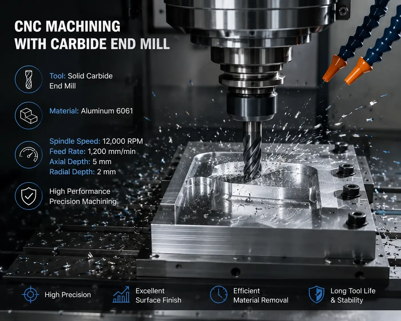
[A CNC machine cutting metal with a carbide end mill]
I get it. Everyone wants a simple chart that just gives them the right numbers. Plug them in and go. But in my years of experience as a tool manufacturer, I've seen that approach lead to more broken tools than successful parts. A chart is like a map, but it's useless if you don't know the specific terrain you're about to cross. Instead of just looking for a number, you need to know what questions to ask first. Let's walk through how we approach this problem so you can get more predictable and reliable results from your tools.
Why Do Standard Feed and Speed Charts Often Fail?
You followed a feed and speed chart perfectly, but the end mill still chattered, chipped, or snapped. This makes you doubt the chart, your machine, and maybe even the tool itself.
Feed and speed charts often fail because they are created for ideal, generic conditions that don't match your unique setup.[2] They cannot account for your machine's actual rigidity, tool holder wear, coolant delivery, or specific material hardness variations, leading to unexpected tool failure.
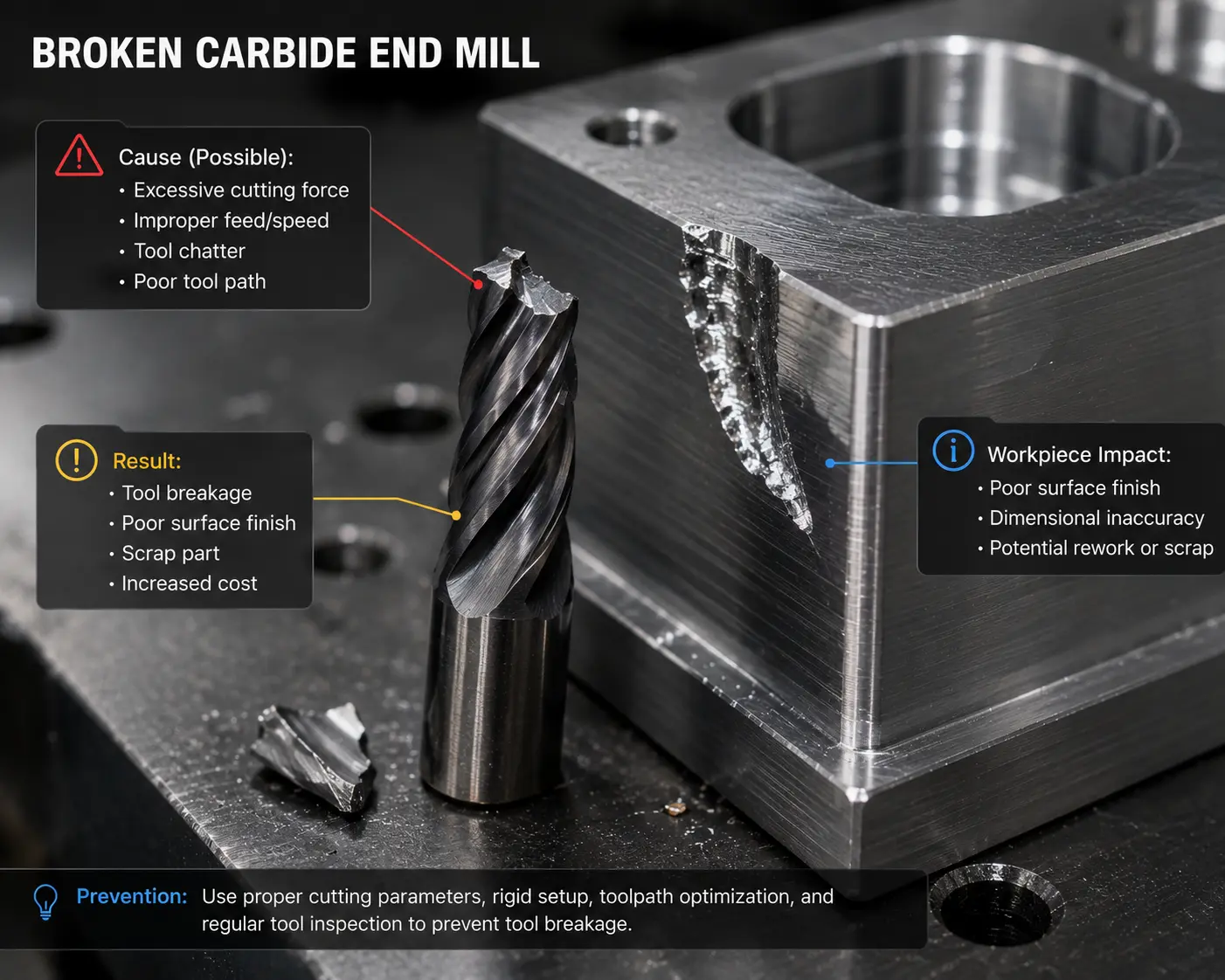
As a manufacturer, we create recommended parameters in a controlled environment. Our test machines are rigid, our tool holders are new, and the material we cut is a known, consistent grade. Your shop floor is the real world, and things are different there. A chart is a great starting point, but it's blind to the variables that have a huge impact on performance. Thinking about these factors is the key to moving from guessing to making educated adjustments.
Here are the main things a simple chart just can't see:
Key Variables Beyond the Chart
Factor | Chart's Assumption | Your Reality | Impact on Parameters |
|---|---|---|---|
Machine Rigidity | A new, heavy-duty, and rigid machine. | An older machine with some wear in the ways. | |
Tool Holding | A new, high-quality collet with near-zero runout. | A slightly worn holder or collet causing runout. | |
Material Batch | A standard material hardness (e.g., 4140 Annealed). | The same material, but pre-hardened or from a different supplier. | |
Coolant Use | Perfect flood coolant application. | Air blast, mist, or even dry machining. | Speed and feed may need to be adjusted to manage heat, especially in deep pockets. |
This is why just copying numbers from a book or website can be a recipe for disaster. The chart isn't wrong; it's just giving you one piece of a much larger puzzle.
What Key Information Determines Your Starting Parameters?
You need to call your tool supplier for advice, but you're not sure what information they need. Giving them vague details often results in a vague, unhelpful answer, which wastes everyone's time.
Before setting any parameters, you need four key pieces of information: the exact workpiece material and its hardness, the type of machining operation, the axial depth of cut (ADOC), and the radial depth of cut (RDOC)[6]. This data is more critical than any generic chart.
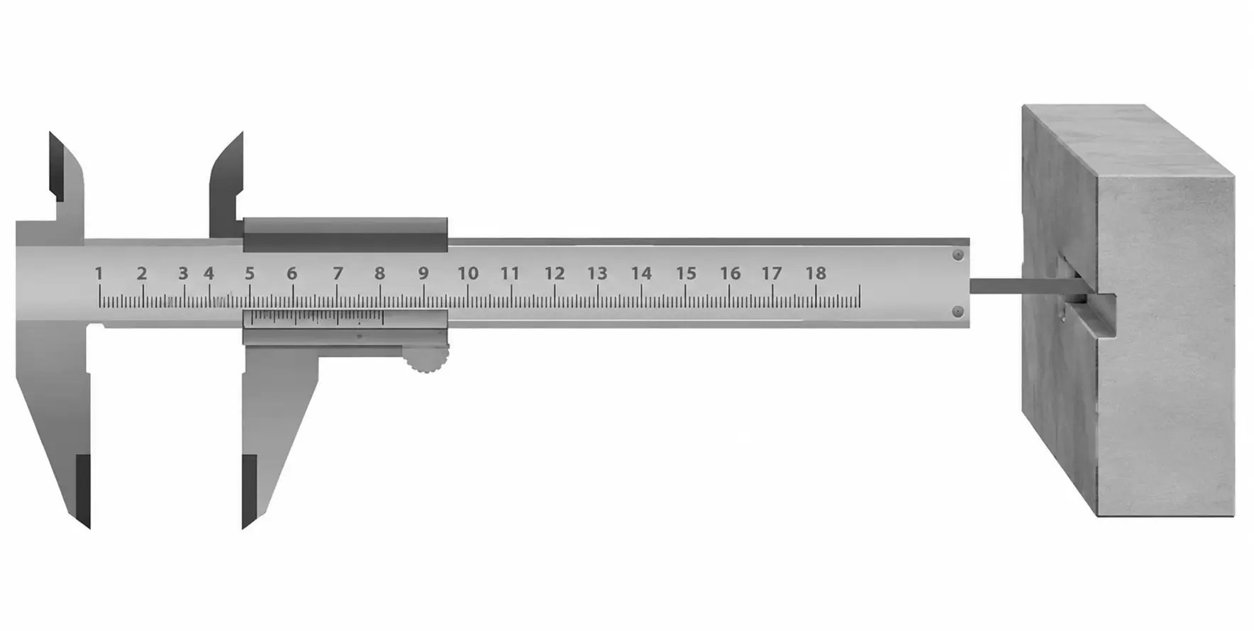
When a customer calls us asking for feed and speed recommendations, these are the first four things we ask for. Without them, any numbers we give are just a wild guess. Having this information ready turns a confusing conversation into a productive one. Let's break down why each of these is so important.
The Four Pillars of Parameter Selection
- Workpiece Material and Hardness: This is the most important factor. Simply saying "steel" is not enough information. Is it soft 1018 mild steel or tough D2 tool steel hardened to 60 HRC? The cutting speed (SFM) for soft steel could be five times higher than for hardened tool steel.[7] Without knowing the exact material and its condition (annealed, pre-hardened, etc.), you can't choose the correct starting RPM.
- Type of Operation: Are you roughing, finishing, or slotting? Each has a different goal. Roughing aims for a high Material Removal Rate (MRR), often using deep cuts. Finishing aims for a smooth surface, using light cuts. Slotting, where the end mill is engaged 180°, is one of the most demanding operations and requires much more conservative parameters than light side milling.[8]
- Axial Depth of Cut (ADOC): This is how deep the tool is cutting along its axis. A deeper cut engages more of the cutting edge, which can increase tool pressure and heat.[9]
- Radial Depth of Cut (RDOC): This is the tool's step-over, or how much it engages with the material on its side. This dramatically changes the game. A full-width slot (100% RDOC) is much harder on the tool than a light profiling pass (10% RDOC).[10] Modern high-efficiency milling (HEM) strategies use a deep ADOC but a very small RDOC, allowing for much higher feed rates than traditional methods.[11]
Machining Strategy | Typical ADOC | Typical RDOC | Feed Rate Goal | |
|---|---|---|---|---|
Traditional Slotting | 0.5 x Diameter | 1.0 x Diameter | Low | Create a slot in one pass |
HEM Roughing | 2.0 x Diameter | 0.1 x Diameter | Very High | Fast material removal |
Finishing Pass | 0.1 x Diameter | 0.4 x Diameter | Moderate | Excellent surface finish |
How Do You Safely Adjust Feeds and Speeds From a Starting Point?
You have your starting parameters, but you're nervous about making changes. Pushing the tool too hard could break it instantly, but being too cautious wastes expensive machine time and hurts productivity.
Start with 50% of the recommended feed rate and 100% of the RPM. Listen for chatter and watch the chips. If the cut is stable and quiet, gradually increase the feed override. If you hear loud noises or see bad chips, make one small adjustment at a time.
Once you have a good starting point based on your material and cut details, the real work begins on the machine. Finding the "sweet spot" is a process of careful, step-by-step optimization. It's not about being aggressive; it's about being observant. I always tell machinists to use their eyes and ears—they are often the best sensors you have. This simple, methodical process will help you find the best parameters for your specific job without risking your tools.
A Practical Guide to Optimization
- Start Conservatively I always recommend starting a new setup with the calculated RPM but setting the machine's feed rate override to 50%. This is your safety net. It gives you time to assess the cut before the tool is under full load. If everything sounds and looks good during the first few seconds of cutting, you can begin to increase the feed.
- Look and Listen for Clues Your machine and workpiece will tell you everything you need to know.
- Sound: A smooth, consistent hum is what you want to hear. A high-pitched squeal often means your speed is too high or your feed is too low. A loud, rhythmic banging or rattling sound is chatter. This is a vibration that will destroy your tool and leave a terrible surface finish. If you hear chatter, the first thing to do is reduce your RPM or your depth of cut.
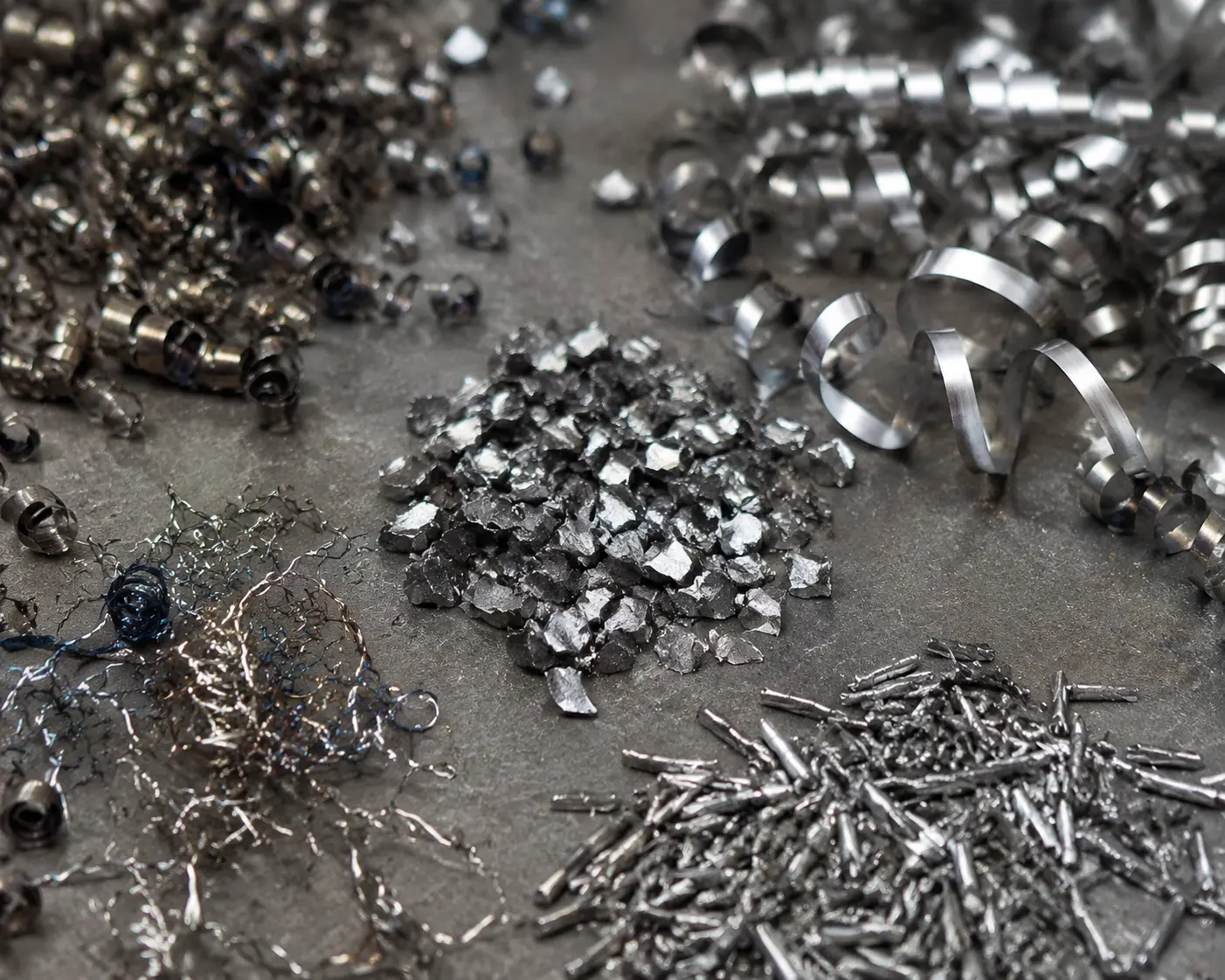
- Chips: The chips are a history of the cut. For steels, you generally want to see chips that are well-formed and have a light straw or golden color, indicating a healthy cutting temperature. If they are dark blue or purple, there is too much heat, and you should lower your RPM. If you're making fine, dust-like powder, your feed rate is too low, and the tool is rubbing instead of cutting. This will wear out the tool very quickly.
- Make One Change at a Time This is critical. If you have chatter and you change both the RPM and the feed rate at the same time, you won't know which change fixed the problem. If the cut is stable, slowly increase the feed rate override back to 100%. If it still sounds good, you can even try pushing it to 110% or 120%. Finding the point where the cut starts to sound harsh and then backing off slightly is how you find the true maximum performance for that specific setup.
Conclusion
Treat feed and speed charts as a starting point, not the final word. Adjust parameters based on your material, setup, and cut data for better tool life and performance.
1
"Turning with shallow cuts at high speeds", https://nvlpubs.nist.gov/nistpubs/jres/3/jresv3n6p829_A2b.pdf. A manufacturing engineering reference describes published cutting data as starting values that must be adapted to the specific tool, workpiece material, machine condition, and cutting operation. Evidence role: expert_consensus; source type: education. Supports: A neutral machining text or university manufacturing resource should support that cutting parameters are selected from recommended starting values and then adjusted for machine, tool, workpiece, and operation conditions.. Scope note: Such a source would support the general parameter-selection principle, not prove the author's specific workflow.
2
"Effect of Cutting Conditions on Roughness and Cutting Force When ...", https://pmc.ncbi.nlm.nih.gov/articles/PMC12985697/. Machining references commonly state that tabulated feed and speed data are conditional values based on specified materials, tools, and cutting environments rather than universal constants. Evidence role: general_support; source type: education. Supports: A source should confirm that tabulated cutting speeds and feeds assume specified reference conditions and must be adjusted when actual conditions differ.. Scope note: This supports the article's general explanation, but not the frequency implied by the phrase 'often fail.'
3
"[PDF] Chatter Stability of Machining Operations", https://mtrc.utk.edu/wp-content/uploads/sites/45/2020/08/manu_142_11_110801.pdf. Research on milling stability shows that chatter depends on the dynamic stiffness of the machine-tool system and on cutting parameters such as spindle speed and depth of cut. Evidence role: mechanism; source type: paper. Supports: A source should explain that chatter in milling is affected by spindle speed, axial or radial depth of cut, and system stiffness, and that changing these variables can move the cut into a stable region.. Scope note: The source would explain why reducing these parameters can help, but exact reductions remain setup-specific.
4
"Research on Cutting Force Modeling and Machining Performance of ...", https://pmc.ncbi.nlm.nih.gov/articles/PMC12388261/. Studies of end-milling runout report that eccentricity changes the chip load carried by individual flutes, producing unequal cutting forces and accelerated local wear. Evidence role: mechanism; source type: paper. Supports: A research source should support that cutter runout changes chip thickness among teeth or flutes and can increase localized cutting forces and wear..
5
"Investigation on Effect of Material Hardness in High Speed CNC End ...", https://pmc.ncbi.nlm.nih.gov/articles/PMC4736218/. Manufacturing texts generally relate increasing workpiece hardness to lower recommended cutting speeds because harder materials raise cutting forces, cutting temperatures, and tool-wear rates. Evidence role: mechanism; source type: education. Supports: A machining reference should explain that harder workpiece materials typically require lower cutting speeds because cutting forces, temperature, and tool wear increase.. Scope note: The source would support the general trend; the amount of reduction depends on the alloy, heat treatment, tool coating, and coolant condition.
6
"Thin Wall Milling at a Maximized Axial Depth of Cut - PMC", https://pmc.ncbi.nlm.nih.gov/articles/PMC12654576/. Machining education resources identify workpiece material properties, operation type, axial depth of cut, and radial engagement as primary variables in selecting milling speeds and feeds. Evidence role: expert_consensus; source type: education. Supports: A neutral educational or handbook source should identify workpiece material, hardness, operation type, axial depth of cut, and radial engagement as major factors in milling parameter selection.. Scope note: The source may not frame them as exactly 'four' pillars, but it should support their technical relevance.
7
"Milling Speeds And Feeds: Charts & Data - 6G Tools", https://www.6gtools.com/technical-info/end-mills/feeds-and-speeds-carbide.html?srsltid=AfmBOoo-ZMP3jrGcFMFafqR5p_zAxf-ZiGTYYcElMV7yDuNMnsDaA-Zw. Published cutting-speed tables for carbide milling list substantially higher surface-speed ranges for low-carbon or annealed steels than for hardened tool steels, supporting the order-of-magnitude comparison. Evidence role: statistic; source type: education. Supports: A machining handbook or educational cutting-speed table should provide SFM ranges showing that mild or annealed steels permit substantially higher cutting speeds than hardened tool steels.. Scope note: The exact fivefold ratio may vary by alloy, hardness, cutter coating, and operation.
8
"Research on Cutting Force Modeling and Machining ... - PMC", https://pmc.ncbi.nlm.nih.gov/articles/PMC12388261/. Milling mechanics literature treats full-slot cutting as a high radial-immersion case in which cutter engagement and cutting forces are greater than in light side milling. Evidence role: mechanism; source type: paper. Supports: A technical source should show that full-slot milling has high radial immersion and cutting-force demands compared with partial radial-immersion side milling.. Scope note: The source would support the mechanical basis for conservative parameters, while the exact parameter reduction remains application-specific.
9
"Thin Wall Milling at a Maximized Axial Depth of Cut - PMC - NIH", https://pmc.ncbi.nlm.nih.gov/articles/PMC12693476/. Milling mechanics studies show that greater axial depth of cut increases the engaged cutting-edge length and is associated with higher cutting forces and thermal load. Evidence role: mechanism; source type: paper. Supports: A source should support that increasing axial depth of cut increases engaged cutting-edge length and can increase cutting forces and heat generation..
10
"Milling Force Modeling: A Comparison of Two Approaches", https://mtrc.utk.edu/wp-content/uploads/sites/45/2019/09/force_model.pdf. Research on milling radial immersion shows that increasing radial depth of cut increases cutter engagement and cutting loads, making full-width slotting more demanding than low-engagement profiling. Evidence role: mechanism; source type: paper. Supports: A source should show that radial depth of cut or radial immersion affects cutter engagement, chip formation, cutting force, and tool load.. Scope note: The phrase 'much harder' is qualitative; the magnitude depends on tool diameter, feed per tooth, material, and toolpath.
11
"[PDF] Helical - MACHINING GUIDEBOOK", https://web.mae.ufl.edu/designlab/Advanced%20Manufacturing/Helical_Machining_Guidebook.pdf. Technical literature on high-efficiency or trochoidal milling describes the strategy as combining low radial immersion with higher axial engagement and increased feed rates compared with conventional roughing. Evidence role: definition; source type: research. Supports: A research or educational source should describe high-efficiency or trochoidal milling as using low radial engagement with higher axial engagement and elevated feed rates to maintain chip load and reduce tool load.. Scope note: The source would support the general strategy; actual feed-rate increases depend on machine dynamics, toolpath control, and workpiece material.